Computer Networking Course - Network Engineering [CompTIA Network+ Exam Prep]
Published July 16, 2023, 6:20 a.m. by Monica Louis
This full college-level computer networking course will prepare you to configure, manage, and troubleshoot computer networks. It will also help you prepare for CompTIA's network+ exam.
This course was developed by Brian Ferrill, an instructor at Edmonds Community College.
⭐️ Course Contents ⭐️
⌨️ (0:00:00) Intro to network Devices (part 1)
⌨️ (0:07:24) Intro to network Devices (part 2)
⌨️ (0:15:12) Networking Services and Applications (part 1)
⌨️ (0:22:49) Networking Services and Applications (part 2)
⌨️ (0:28:17) DHCP in the network
⌨️ (0:38:03) Introduction to the DNS Service
⌨️ (0:46:01) Introducing network Address Translation
⌨️ (0:52:52) WAN Technologies (part 1)
⌨️ (1:03:02) WAN Technologies (part 2)
⌨️ (1:09:32) WAN Technologies (part 3)
⌨️ (1:17:20) WAN Technologies (part 4)
⌨️ (1:22:32) network Cabling (part 1)
⌨️ (1:31:24) network Cabling (part 2)
⌨️ (1:38:15) network Cabling (part 3)
⌨️ (1:43:28) network Topologies
⌨️ (1:50:29) network Infrastructure Implementations
⌨️ (1:56:26) Introduction to IPv4 (part 1)
⌨️ (2:02:42) Introduction to IPv4 (part 2)
⌨️ (2:15:58) Introduction to IPv6
⌨️ (2:26:10) Special IP Networking Concepts
⌨️ (2:34:06) Introduction to Routing Concepts (part 1)
⌨️ (2:40:00) Introduction to Routing Concepts (part 2)
⌨️ (2:49:29) Introduction to Routing Protocols
⌨️ (2:59:01) Basic Elements of Unified Communications
⌨️ (3:04:27) Virtualization Technologies
⌨️ (3:09:24) Storage Area Networks
⌨️ (3:15:33) Basic Cloud Concepts
⌨️ (3:21:43) Implementing a Basic network
⌨️ (3:31:02) Analyzing Monitoring Reports
⌨️ (3:40:03) network Monitoring (part 1)
⌨️ (3:48:14) network Monitoring (part 2)
⌨️ (3:55:10) Supporting Configuration Management (part 1)
⌨️ (4:01:52) Supporting Configuration Management (part 2)
⌨️ (4:07:19) The Importance of network Segmentation
⌨️ (4:14:18) Applying Patches and Updates
⌨️ (4:19:52) Configuring Switches (part 1)
⌨️ (4:26:39) Configuring Switches (part 2)
⌨️ (4:36:27) Wireless LAN Infrastructure (part 1)
⌨️ (4:46:42) Wireless LAN Infrastructure (part 2)
⌨️ (4:53:17) Risk and Security Related Concepts
⌨️ (5:00:46) Common network Vulnerabilities
⌨️ (5:09:49) Common network Threats (part 1)
⌨️ (5:17:13) Common network Threats (part 2)
⌨️ (5:26:33) network Hardening Techniques (part 1)
⌨️ (5:36:00) network Hardening Techniques (part 2)
⌨️ (5:44:40) network Hardening Techniques (part 3)
⌨️ (5:50:58) Physical network Security Control
⌨️ (5:57:19) Firewall Basics
⌨️ (6:06:53) network Access Control
⌨️ (6:13:22) Basic Forensic Concepts
⌨️ (6:22:42) network Troubleshooting Methodology
⌨️ (6:29:18) Troubleshooting Connectivity with Utilities
⌨️ (6:36:32) Troubleshooting Connectivity with Hardware
⌨️ (6:43:39) Troubleshooting Wireless Networks (part 1)
⌨️ (6:50:56) Troubleshooting Wireless Networks (part 2)
⌨️ (6:57:27) Troubleshooting Copper Wire Networks (part 1)
⌨️ (7:03:49) Troubleshooting Copper Wire Networks (part 2)
⌨️ (7:09:19) Troubleshooting Fiber Cable Networks
⌨️ (7:14:43) network Troubleshooting Common network Issues
⌨️ (7:24:40) Common network Security Issues
⌨️ (7:35:12) Common WAN Components and Issues
⌨️ (7:43:33) The OSI Networking Reference Model
⌨️ (7:51:50) The Transport Layer Plus ICMP
⌨️ (7:58:35) Basic network Concepts (part 1)
⌨️ (8:05:33) Basic network Concepts (part 2)
⌨️ (8:12:29) Basic network Concepts (part 3)
⌨️ (8:17:42) Introduction to Wireless network Standards
⌨️ (8:24:26) Introduction to Wired network Standards
⌨️ (8:32:41) Security Policies and other Documents
⌨️ (8:40:08) Introduction to Safety Practices (part 1)
⌨️ (8:48:34) Introduction to Safety Practices (part 2)
⌨️ (8:54:26) Rack and Power Management
⌨️ (9:00:25) Cable Management
⌨️ (9:05:56) Basics of Change Management
⌨️ (9:12:11) Common Networking Protocols (part 1)
⌨️ (9:18:06) Common Networking Protocols (part 2)
You may also like to read about:
Hi, I'm Bo with Free Code Camp. This network engineering course was developed by Brian
Farrell, and instructor with Edmonds college. It will prepare you to configure, manage and
troubleshoot computer networks. Also, the course is a great way to prepare for a comp
Tia's network plus exam. So let's start. Hello, I'm Brian ferrill. And welcome to pace I t's
session on the introduction to network devices, part one. Today we're going to be talking
about layer one devices, layer two devices. And then we're going to conclude with layer
three devices. There's a fair amount of information to cover. So let's go ahead and dive into
this session. Of course, I'm going to begin with layer one devices. Well, before I start
talking about the layer one devices, we need to talk about the open system interconnection
model, the OSI model, it was developed as a way to help disparate computing systems
to communicate with each other. The OSI reference model has seven layers. layer one is the physical
layer, layer two is data link. layer three is network layer four is transport layer five
is session. Layer six is presentation and layer seven is application. We're going to
be discussing the bottom three layers layers One, two and three today. Now most devices
do function at more than one layer of the OSI reference model. But when it comes time
to determining where they fit into the model, you must first determine the highest level
at which they operate, because that's where they fit into the OSI model. To do that, you
must know what they do and how that relates to the OSI model. And with that, let's talk
about analog modems. The word modem is actually derived from a contraction of modulator demodulator.
modems were developed to take a digital signal coming from a digital node and convert it
to an analog signal modulating the signal and placing it on a wire. In return, it would
accept an analog signal from the wire and convert it demodulating the signal back to
a digital signal that the node can understand. modems were developed to create a connection
between network segments via the public switched telephone network using the plain old telephone
system. Now modems provide for a single connection to a network. And they're only concerned about
the wire in the wire resides on the physical layer layer one of the OSI model, it doesn't
care where the signal comes from, it just does its job. Then there's the hub. A hub
functions as a concentrator or repeater in that it doesn't care where the signal comes
from, or where the signal is going. Kind of like the modem, it takes an electrical signal
that arrives on a port and replicates that signal out all of its other ports. hub may
have just a few ports, or it may have many ports in for a variety of reasons the hub
is not very common anymore in the modern network. So now let's move on to layer two devices.
The first layer two device that we're going to talk about is the switch. A switch utilizes
an application specific integrated circuit chip and a basic chip. The ASIC chip has specific
programming that allows the switch to learn when a device is on the network and which
ports it is connected to via that devices layer two MAC address. That's what makes a
switch a layer two device, a switch may have just a few ports or it may have many ports,
kind of like the hub. And although a switches smarter than a hub, it can still be very simple,
or it can be highly complex and programmable. A switch can only communicate with local network
devices. another layer two device that we need to talk about our wireless access points.
The whap whap is a specific type of network bridge that connects or bridges, wireless
network segments with wired network segments. The most common type of web bridges and 802
dot 11 wireless network segment with an 802 dot three Ethernet network segment just like
a switch a wire Access Point will only communicate with local network devices. Now let's move
on to layer three devices. And First up is the multi layer switch. A multi layer switch
provides normal layer two network switching services, but it will also provide layer three
or higher OSI model services. The most common multi layer switch is a layer three switch,
it not only utilizes an async chip for switching, but that async chip is also programmed to
handle routing functions. This allows the device to communicate and pass data to non
local network devices. A multi layer switch is a highly programmable and complex network
device. A multi layer switch may have just a few ports, or it may have a lot of ports.
They're not very common in the small office home office network. Because they're really
really expensive, you're more likely to find them in an enterprise local area network.
Now let's move on to the router. A router is the most common network device for connecting
different networks together, utilizing the OSI models layer three logical network information.
That's what makes a router a layer three device. The router uses software programming for decision
making, as compared to the switches use of an ASIC chip. The router uses this programming
to keep track of different networks in what it considers to be the best possible route
to reach those networks. A router can communicate with both local and non local network devices.
In most cases, a router will have fewer ports, then a switch. Now that concludes this session
on the introduction to network devices. Part One, we talked about layer one devices. We
talked about layer two devices. And we concluded with a couple of layer three devices. Good
day. I'm Brian ferrill. And welcome to pace eyeties session on introduction to network
devices, part two. Today we're going to discuss some security network devices. And then we'll
move on to some optimization and performance devices. And with that, let's go ahead and
begin this session. And we will begin by talking about security devices. First up is the firewall.
Now a firewall can be placed on routers or hosts in that it can be software based or
it can be its own device. A firewall functions at multiple layers of the OSI model, specifically
at layers 234 and seven. A firewall can block packets from entering or leaving the network.
And it does this through one of two methods it can do it through stateless inspection,
in which the firewall will examine every packet that enters or leaves the networks against
a set of rules. Once the packet matches a rule, the rule is enforced in the specified
action is taken, or it may use state full inspection. This is when a firewall will only
examine the state of a connection between networks. Specifically, when a connection
is made from an internal network to an external network. The firewall will not examine any
packets returning from the external connection. It only cares about the state of the connection.
As a general rule, external connections are not allowed to be initiated with the internal
network. Now firewalls are the first line of defense in protecting the internal network
from outside threats. You can consider the firewall to be the police force of the network.
Then there is the intrusion detection system. The IDs and IDs is a passive system designed
to identify when a network breach or attack against the network is occurring. They're
usually designed to inform a network administrator when a breach or attack has occurred. And
it does this through log files, text messages and are through email notification Friends,
and IDs cannot prevent or stop a breach or attack on its own. The IBS receives a copy
of all traffic and evaluates it against a set of standards. The standards that it used
may be signature based. This is when it evaluates network traffic for known malware or attack
signatures, or the standard may be anomaly based. This is where it evaluates network
traffic for suspicious changes, or it may be policy base. This is where it evaluates
network traffic against a specific declared security policy. An IDs may be deployed at
the host level when it's deployed at the host level. It's called a host based intrusion
detection system, we're hids more potent than the intrusion detection system is the intrusion
prevention system. The IPS an IPS is an active system designed to stop a breach or attack
from succeeding and damaging the network. They're usually designed to perform an action
or set of actions to stop the malicious activity. They will also inform a network administrator
through the use of log files, SMS, text messaging, and or through email notification. For an
IPS to work. All traffic on the network segment needs to flow through the IPS as it enters
and leaves the network segment. Like the IDS all of the traffic is evaluated against a
set of standards and they're the same standards that are used on the IDs. The best placement
on the network segment is between a router with a firewall hopefully, and the destination
network segment. That way all the traffic flows through the IPS. IPS are programmed
to make an active response to the situation, they can block the offending IP address, they
can close down vulnerable interfaces, they can terminate network sessions, they can redirect
the attack. Plus there are more actions that an IPS can take. The main thing is is that
they are designed to be active to stop the breach or attack from succeeding and damaging
your network. Let's move on to the virtual private network concentrator the VPN concentrator.
Now this will allow for many secure VPN connections to a network. The concentrator will provide
proper tunneling and encryption depending upon the type of VPN connection that is allowed
to the network. Most concentrators can function at multiple layers of the OSI model. Specifically,
they can operate at layer two, layer three and layer seven. Now outside of internet transactions,
which use an SSL VPN connection at layer seven, most concentrators will function at the network
layer or layer three of the OSI model, providing IPsec encryption through a secure tunnel.
Now let's talk about optimization and performance devices. We will begin by talking about the
load balancer. a load balancer may also be called a content switch or a content filter.
It's a network appliance that is used to load balance between multiple hosts that contain
the same data. This spreads out the workload for greater efficiency. They're commonly used
to distribute the requests or workload to a server farm among the various servers in
the farm, helping to ensure that no single server gets overloaded with work requests.
Then there's the proxy server. A proxy server is an appliance that requests resources on
behalf of a client machine. It's often used to retrieve resources from outside untrusted
networks on behalf of the requesting client. It hides and protects that requesting client
from the outside untrusted network. It can also be utilized to filter allowed content
back into the trusted network. It can also increase network performance by caching or
saving commonly requested web pages. Now that concludes this session on the introduction
to network devices, part two We talked about some security devices that you may find on
your network. And we concluded with optimization and performance devices that may also be present.
Hello, I'm Brian ferrill. And welcome to pace I t's session on networking services and applications
part one. Today I'm going to be discussing the basics of the virtual private network.
And then I'm going to move on to protocols used by virtual private networks. Now, there's
a whole lot of stuff to cover. So let's go ahead and begin this session. Of course, I'm
going to begin by talking about the basics of the virtual private network. A virtual
private network or VPN is used by remote hosts to access a private network through an encrypted
tunnel through a public network. Once the VPN connection is made, the remote host is
no longer considered remote is actually seen by the private network as being a local host.
There are many advantages to that, but I'm not going to cover them right now. Even though
the network traffic may pass through many different routes or systems, it's seen by
both ends as being a direct connection. The use of the VPN can help to reduce networking
costs. For organizations and business. The cost reduction is partially achieved, because
the VPN doesn't require the use of a dedicated leased line to create that direct connection.
There are several different types of VPNs there is the site to site VPN, which allows
a remote sites network to connect to the main sites network and be seen as a local network
segment. VPN concentrators on both ends of the VPN will manage that connection. Then
there's the remote access VPN, which is also called a host to site VPN. It allows select
remote users to connect to the local network. A VPN concentrator on the local network will
manage the connection coming in from the remote users. The remote system making the connection
uses special software called VPN client software to make that connection. The third type of
VPN is the host of host VPN, which is often called an SSL VPN. It allows us secure connection
between two systems without the use of VPN client software. A VPN concentrator on the
local network manages the connection. The host seeking to connect uses a web browser
that supports the correct encryption technology, which is either SSL or more likely TLS. To
make the connection to the VPN concentrator. It's time to discuss some protocols used by
the virtual private network. The big protocol for VPN is called Internet Protocol security
IPsec, which isn't actually a protocol in itself, but a whole set of protocols. IP sec
works at layer three of the OSI model or above. It's the most common suite of protocols used
to secure a VPN connection. IP sec can be used with the authentication header protocol
or the H protocol. h only offers authentication services, but no encryption. So it authentic
Kate's the user but there is no encryption of the session, or ipset can be used with
encapsulating security payload protocol or the ESP protocol. ESP both authenticates and
encrypts the packets. It is the most popular method of securing a VPN connection, both
H and ESP will operate in one of two modes. The first mode is transparent mode, that is
between two devices as in a host to host VPN, or they can be used in tunnel mode, which
is between two endpoints as in a site to site VPN, IP sec implements Internet Security Association
and key management eisah camp by default eisah camp provides a method for transferring security
key and authentication data between systems outside of the security key generating process.
It is a much more secure process. Then we have generic routing encapsulation. gra G
is a tunneling protocol that is capable of encapsulating a wide variety of other nuts
layer protocols, it's often used to create a sub tunnel within an IP sec connection.
Why is that? Well, IP sec will only transmit unicast packets, that's one to one communication.
In many cases, there is a need to transmit multicast, which is one to some communication,
or broadcast, which is one to many communication packets across an IP set connection. By using
GRP we can get that accomplished. Then there's Point to Point tunneling protocol pptp. This
is an older VPN technology that supports dial up VPN connections. on its own, it lacked
native security features, so it wasn't very secure. But Microsoft's implementation included
additional security by adding gr E. Two point to point tunneling protocol. Transport Layer
Security is another common VPN protocol. TLS is a cryptographic protocol used to create
a secure encrypted connection between two end devices or applications. It uses asymmetrical
cryptography to authenticate endpoints and then negotiates a symmetrical security key,
which is used to encrypt the session TLS has largely replaced its cousin, secure socket
layer protocol, and TLS works at layer five and above of the OSI model. Its most common
usage is in creating a secure encrypted internet session or SSL VPN. All modern web browsers
support TLS now I just mentioned secure socket layer or SSL. SSL is an older cryptographic
protocol that is very similar to TLS. The most common use is in internet transactions.
Why? Because all modern web browsers support SSL. But due to issues with earlier versions
of the protocol, it has largely been replaced by TLS. SSL version 3.3 has been developed
to address the weaknesses of earlier versions. But it may never again catch up to its cousin,
the TLS protocol. Now that concludes this session on networking services and applications
part one, I talked about the basics of the virtual private network. And then I talked
about the protocols used by the VPN network. Good day, I'm Brian ferrill. And welcome to
pace I t's session on networking services and applications part two. Today we're going
to be discussing network access services. And then we're going to move on to other services
and applications. As always, there's a fair amount of ground to cover. So let's go ahead
and dive into this session. I will begin with network access services. The first network
access service that I'm going to discuss is actually a piece of hardware, the network
interface controller or Nic, it can also be called the network interface card. The Nic
is how a device connects to a network. The network interface controller works at two
layers of the OSI model at layer two which is the data link layer. It provides the functional
means of network communication by determining which networking protocols will be used as
in a Nic that will provide Ethernet communication or Nic that will provide Point to Point protocol.
It also provides the local network node address through its burned in physical media access
control address at layer one the physical layer, the network interface controller determines
how the network data traffic will be converted a bit at a time into an electrical signal
that can traverse the network media being used, ie it provides the connection to the
network. Most modern computers come with at least one built in Ethernet Nic routers and
other network devices may use separate modules that can be inserted into the device to provide
the proper network interface controller for the type of media they're connecting to in
the networking protocols that are being used. Another network access service is radius remote,
authentic dial in user service radius is a remote access service that is used to authenticate
remote users and grant them access to authorized network resources. It is a popular triple
A protocol that's authentication, authorization and accounting protocol. It's used to help
ensure that only authenticated end users are using the network resources they are authorized
to use. The accounting services of radius are very robust. The only drawback to radius
is only the requesters the end users password is encrypted. Everything else gets sent in
the clear terminal access controller access control system plus or TAC x plus terminal
access controller access control system plus point what a mouthful, it sure is easier to
say. TAC x plus is a remote access service that is used with authenticate remote devices
and grant them access to authorized network resources. It is also a popular triple A protocol
used to help ensure that only authenticated remote network devices are using the network
resources that they are authorized to use. With TAC x plus the accounting features are
not as robust as those found in radius. But all network transmissions between devices
are encrypted with TAC x plus, let's move on to other services and applications. First
up is our AAS Remote Access Services. Now, RS is not a protocol, but a roadmap. Rs is
a description of the combination of software and hardware required for remote access connection.
A client requests access from an RS server, which either grants or rejects that access.
Then we have web services, creating a means of cross communication. Web Services provides
the means for communication between software packages or disparate platforms. It's usually
achieved by translating the communication into an XML format, or Extensible Markup Language
format. It is becoming more popular as systems diverged. Last up is unified voice services.
This is creating a better voice communication system. It's a description of the combination
of software and hardware required to integrate voice communication channels into a network
as in Voice over IP. That concludes this session on networking services and applications. Part
Two. I began by talking about network access services. And I concluded with other services
and applications. Hello, I'm Brian ferrill. And welcome to pace eyeties session on DHCP
in the network. Today, we're going to be talking about static versus dynamic IP addressing.
Then we're going to move on to how DHCP works. And then we will conclude with components
and processes of DHCP. And with that, let's go ahead and begin this session. And of course,
we begin by talking about static versus dynamic IP addresses. So how does a computer know
what its IP configuration is? Well, more than likely a computer received its IP configuration
from a Dynamic Host Configuration Protocol server. Not only did the server give the PC
an IP address, but it also told the PC where the default gateway was, and more than likely
how to find a DNS server, a computer will receive its IP configuration in one of two
ways. Either statically, which means manually set or dynamically, which means through a
service like DHCP static IP address assignment works fine for very small and stable networks,
but quickly becomes unwieldly and error prone as the network grows and more nodes come on
to the network. So let's talk a little bit more about static IP addresses. The administrator
assigned An IP number and subnet mask to each host in the network, whether it be a PC, router
or some other piece of electronic equipment. Each network interface that is going to be
available to connect to the network requires this information. The administrator also assigns
a default gateway location and DNS server location to each host in the network. Now
these settings are required if access to outside networks is going to be allowed, that would
be through the default gateway. And if human friendly naming conventions are going to be
allowed, and that way, you can more easily find network resources, and that would be
through a DNS server. Now each time a change is made, as in a new default gateway is established,
each IP configuration on each host must be updated. That's why it becomes rather cumbersome
and complicated as the network grows. Now with dynamic IP addressing the administrator
configures, a DHCP server to handle the assignment process, which actually automates the process
and eases management. The DHCP server listens on a specific port for IP information requests.
Once it receives a request, the DHCP server responds with the required information. Now
let's move on to how DHCP works. Here is the typical DHCP process. Upon boot up a PC that
is configured to request an IP configuration sends a DHCP discovery packet. Now the discovery
packet is sent to the broadcast address 255255255255 on UDP port 67. The DHCP server is listening
to that port. It's listening for that discovery packet. When the DHCP server receives the
discovery packet, it responds with an offer packet, basically saying hey, I'm here to
help. Now the offer packet is sent back to the MAC address of the computer requesting
help, and it's sent on port 68. Once the computer receives that offer packet from the DHCP server,
if it's going to use that DHCP server, it returns a request packet. That means it's
requesting the proper IP configuration from that specific DHCP server. Once the DHCP server
receives the request packet, it sends back an acknowledgment packet. Now this acknowledgement
packet contains all of the required IP configuration information. Once the PC receives the acknowledgment
packet, the PC changes its IP configuration to reflect the information that it received
from the DHCP server. And that's the typical DHCP process in a nutshell. Now let's talk
about components and the process of DHCP. We're going to begin by talking about the
port's use. Now, I already mentioned this once, but I'm going to mention it again because
you need to know this. The PC sends its discovery packet out on the broadcast address 255255255255
on port 67. That's UDP port 67. When the DHCP server responds, it responds to the PCs MAC
address, Media Access Control address on UDP port 68. That's important. Remember the PC
uses UDP port 67. The DHCP server responds on UDP port 68. Then there's the address scope.
The address scope is the IP address range that the administrator configures on the DHCP
server. It is the range of addresses that the DHCP server can hand out to individual
nodes. There's also what are called address reservations. Now these are administrator
configured reserved IP addresses. The administrator reserves specific IP addresses to be handed
out to specific MAC addresses. Now these are used for devices that should always have the
same IP address. As in servers and routers. If you did Do that there is the possibility
that your default gateways IP address might change. Now the reason we use address reservation
is this allows these addresses to be changed from a central location, instead of having
to log into each device and change the IP configuration separately. Now part of the
DHCP process are what are called leases. The DHCP server hands out that IP configuration
information, but it sets a time limit for how long that IP configuration is good. This
is called the lease. So the parameters are only good for a specified amount of time.
Now the administrator can configure how long the leases are, there are also options that
the administrator can configure. The first one that's pretty obvious is the default gateway
location. There's also the DNS server address, and the administrator can configure more than
one DNS server location. And administrator can also configure an option for the PC to
synchronize with a time server. So the administrator can configure a time server address. There
are many more additional options, but those are the big three that you should remember.
Now when a PC boots up, it does have a preferred IP address, that would be the IP address that
it had the last time it booted up. Now he can request that same IP configuration from
the DHCP server. Now the administrator can configure the DHCP server to either honor
that preference or to ignore it. Now under the right circumstances, a DHCP server isn't
required to reside on the local network segment. Now as a general rule, broadcast transmissions
cannot pass through a router. But if there's not a DHCP server on the local network segment,
the router can be configured to be a DHCP relay. When a DHCP relay, also called an IP
helper receives a discovery packet from a node, it will forward that packet to the network
segment on which the DHCP server resides. This allows for there to be fewer configured
DHCP servers in any given network, reducing the amount of maintenance that an administrator
needs to perform. Now that concludes this session on DHCP in the network, we started
with static versus dynamic IP addressing. And then we moved on to how DHCP works. And
we concluded with components and processes of DHCP. Hello, I'm Brian ferrill, and welcome
to pace it session on the introduction to the DNS service. Today we're going to be talking
about DNS servers, DNS records, and we will conclude with a brief discussion on dynamic
DNS. And with that, let's go ahead and begin this session. We're going to begin this session
with a talk about DNS servers. Now DNS is the process that maps human friendly names
as in www.google.com, to their appropriate IP addresses. Without DNS we would have to
memorize all of the IP addresses that we wished to visit. Now, DNS stands for Domain Name
System, and it's very structured in nature. If the local DNS server apparatus doesn't
contain the needed record, it sends the request up the DNS chain until the positive response
is received back. Now this positive response gets passed back down to the original requester.
Now DNS does require that an F q dn fully qualified domain name is used in order for
it to function properly known Fq dn is the www.google.com it's that naming convention
right there. The www is the specific service that's being requested. The Google portion
is the local domain that contains the specific service. And the calm is the top level that
contains the Google that contains the specific service that is an F q dn. Now that we've
got that covered, let's talk about the different levels of DNS servers. First off, there can
be a local DNS server. This is the server on the local network that contains the hosts
file that map's all of the Fq DNS to their specific IP addresses in the local sub domain,
it may be present or it may not be present. Then there are top level domain servers, the
TLD server. Now, these are the servers that contain the records for the top level domains,
examples of top level domains are.com.org dotnet.edu, so on and so forth. Now, each
of these servers contains all of their information for their respective domains kind of in what
do I mean by kind of, well, the TLD servers do delegate down to second level servers,
their information, they do that to ease the load so that the TLD server is not overloaded.
But the TLD server is the server that is responsible for maintaining the record. Then there's the
root server. This is the server that contains all of the records for the TLD servers. So
if you're looking for a TLD, that is kind of unknown, you will actually go to the root
server, which will then pass you on to the appropriate TLD. Then there are authoritative
servers and non authoritative servers. And authoritative DNS server is one that responds
to a request. And that authoritative server has been specifically configured to contain
the requested information. an authoritative response comes from a DNS server that actually
holds the original record. So an authoritative response comes from the name server that's
been specifically configured to contain that record, then there are non authoritative DNS
servers. Now a non authoritative DNS server is one that responds to to a request with
DNS information that it received from another DNS server. A non authoritative response is
not a response from the official name server for the domain. Instead, it is a second or
third hand response that's given back to the requester. In most cases, when we send a DNS
request, we get a non authoritative response back. Now let's move on to the various DNS
record types. The first record that we're going to talk about is the a record. Now the
a record maps host names are Fq DNS to their respective ipv4 addresses. closely associated
with the a record is the a record or quadruple a record this maps that Fq dn to its respective
ipv6 address. Then there's the C name record. Now, this maps a canonical name or alias to
a hostname. What that means is that you can have edcc.edu be the same as EDC dot o r g
without having to maintain two sites, the EDC c dot o r g can be the canonical name
for EDC c.edu. This works in part because of the pointer record the PTR record. It's
a pointer record that points out to DNS that there is a canonical name. And finally, we
have the MS record. Now, this record maps to the email server that is specified for
a specific domain. It is the record that determines how email travels from sender to recipient.
And now let's move on to dynamic DNS. Now dynamic DNS or DNS permits lightweight in
immediate updates to a local DNS database. This is very useful for when the Fq dn or
hostname remains the same, but the IP address is able to change on a regular basis. Dynamic
DNS is implemented as an additional service to DNS and it's implemented through DD ns
updating. Now this is a method of updating traditional names. without the intervention
of an administrator, so there's no manual editing or inputting of the configuration
files required. A ddns provider supplies software that will monitor the IP address of the reference
system. Once the IP address changes, the software sends an update to the proper DNS server.
DNS is useful for when access is needed to a domain whose IP address is being supplied
dynamically by an ISP or internet service provider. That way the IP address can change
But people can still get to the service that they're looking for. Now, that concludes this
session on the introduction to the DNS service. We talked about DNS servers, we moved on to
DNS records. And then we concluded with a very brief discussion about dynamic DNS. Hello,
I'm Brian ferrill, and welcome to pace it session introducing network address translation.
Today, we're going to be talking about the purpose of network address translation. And
then we're going to discuss how network address translation works. And with that, let's go
ahead and begin this discussion. Of course, we're going to begin by talking about the
purpose of network address translation. network address translation, or Nat solves a very
serious problem of how to route non routable IP addresses. As a partial effort to conserve
the ipv4 address space, the private ipv4 addressing spaces were developed, these address spaces
were removed from the public ipv4 address space and made non routable across public
ipv4 networks. And this led to the problem being non routable prevents that private ipv4
address from communicating with remote public networks. NAT very simply solves this problem.
A router with Nat enabled will translate a private IP address into a routable public
IP address. When the response returns to the router, it passes the response back to the
device that requested it. So now that we've covered the purpose, let's talk about how
network address translation works. In First off, we get to talk about the fact that there
are two categories of Nat. First up is static Nat. With static Nat each private IP address
is assigned to a specific routable public IP address this relationship is kept and maintained
by the NAT enabled router. When a device needs access outside of the local network. The router
translates the local IP address to the assigned public IP address. And when the response comes
back, the router will translate the public IP address back into a local one. Static Nat
is not flexible in leads to some scalability issues. An individual routable IP address
must be kept for every device that requires access outside of the local network. So as
the network grows, you need to increase the amount of public IP addresses that are under
your control. That gets kind of expensive and kind of complicated. They developed dynamic
Nat to resolve some of that issue. With dynamic Nat the NAT enabled router dynamically assigns
a routable IP address to devices from a pool of available IP addresses. When a device needs
access outside of the local network. The router performs the NAT function only the public
IP address comes from a reusable pool of public IP addresses. That private IP address is assigned
the public IP address from the pool and once outside accesses stop the routable IP address
goes back into the pool to be reused. As initially designed dynamic Nat was more flexible than
static Nat, but it still led to some scalability issues. As more network traffic required access
to outside networks. The pool of available public IP addresses needs to increase or outside
Access cannot be achieved. But thankfully, there is a solution to this. And that solution
is called port address translation, or in Cisco terms, that would be net with Pat. Pat
is a type of dynamic Nat that was developed to increase the scalability of network address
translation. When a local network device requires access to a public network, the net enabled
router dynamically assigns the public IP address to the device. With the addition of dynamically
assigning a port number to the end of the public IP address. The router tracks the IP
addresses important numbers to ensure that network traffic is routed to and from the
proper devices. Pat still requires a pool of public IP addresses. But the pool may only
contain one public IP address, or it may contain several for a large private network. This
is the preferred method of implementing network address translation for two reasons. First
off, there's less public IP addresses that are required. And it makes it easier for an
administrator to maintain. Now let's talk about Nat terminology, specifically about
the types of addresses. And we begin with the inside a local address, which is a private
IP address on the local network. It is the private IP address assigned to a specific
device. Then there's the inside global address a public address referencing an inside device.
The inside global address is the public IP address assigned to the inside device by the
NAT enabled router allowing access outside of the network. Then there's the outside global
address, which is a public IP address referencing an outside device. It is the public IP address
assigned to a device outside of the local network. Then there's the outside local address,
which is the private IP address assigned to an outside device. This is the private IP
address assigned to the outside device by the NAT enabled router on the interior of
the local network so that the inside device can communicate correctly with the outside
device. Now that concludes this session on introducing network address translation. We
talked about the purpose of network address translation. And then we talked about how
network address translation works. Good day. I'm Brian ferrill. And welcome to pace eyeties
session on wind technologies part one. Today I'm going to be talking about the public switched
telephone network. Then I'm going to move on to broadband cable. And I'm going to conclude
with a brief section on fiber optics. And with that, let's go ahead and begin this session.
Of course, we begin with the public switched telephone network. Before I begin with the
public switched telephone network, let's talk about what makes a win a win as opposed to
a LAN. Well, as a general rule, if you own and control the line that the data is using
to get from one place to another, you are not using a wide area network or when technology.
On the other hand, if you are using a form of transmission that you don't own, as in
you're leasing a line or you're paying for the use of it, then you are likely using when
technology. One of the most common physical infrastructures used in wind technology is
the public switched telephone network, the PSTN due to its widespread availability, just
about everybody has a telephone line being run to their house or to their building. An
older technology but still somewhat valid today for when technology is dial up. No dial
up utilizes the PSTN to transmit network traffic as an analog signal. dial up does require
an analog modem to format the network traffic correctly so it can be transmitted. Your maximum
theoretical speed on dial up is 56 kilobits per second. It's not very fast. Then there's
ISDN integrated service. Digital Network ISDN is a digital point to point when technology
that utilizes the PSTN. It's a completely digital service, it requires the use of a
terminal adapter or ta to make the connection to the end nodes. This ta is often called
a digital modem, but it's not it's a terminal adapter ISDN can use a primary rate interface
or pri. Now the PRI is composed of 2364 kilobit per second B channels and once 64 kilobit
per second D channel that D channel is used for call setup in link management. A pri can
achieve 1.544 megabits per second speed, and that is commonly referred to as a T one leased
line. The most commonly implemented form of an ISDN though is the Bri the basic rate interface,
it uses only two B channels and one D channel, and the Bri can achieve speeds of up to 128
kilobits per second. Now ISDN is not as capable as a digital subscriber line or DSL, but it
can often be implemented where DSL cannot be installed. Speaking about DSL, let's move
on to it. xx DSL is the term for generic DSL. DSL is a digital wind technology that utilizes
the PSTN DSL does require the use of a digital modem. It uses a dedicated digital line between
the endpoint in a class five central office or CEO. Now in order for the most basic forms
of DSL to be installed, you have to be within 18,000 feet of the CEO. DSL is capable of
carrying voice and data. When it does carry both filters are put in place in order for
the voice signal to come through without any interference. Now let's move on to the different
types of DSL. In First up is symmetric DSL or sdsl. symmetric DSL is synchronous in nature.
That means that the upload and download speeds are the same as DSL does not carry voice communication.
So if you need voice service, an additional line is going to be needed. As DSL is used
by businesses that don't quite need the performance of a T one leased line, but they do require
the symmetrical upload and download speeds. more common than sdsl is ADSL or asymmetric
DSL, it's asynchronous in nature. That means that the upload speed is slower than the download
speed. ADSL can carry data and voice common upload speeds for ADSL are 768 kilobits per
second, with download speeds of up to nine megabits per second. It is the most common
implementation of DSL, in the small office home office environment. Last up for DSL is
VDSL are very high bitrate DSL, it's asynchronous in nature as well. It's used when high quality
video in Voice over IP is necessary. VDSL is commonly limited to download speeds of
52 megabits per second with an upload speed of 12 megabits per second. That's a whole
lot faster than ADSL. But VDSL is only possible when you're located within 4000 feet of a
central office. There is an exception to what I just told you though, the current standards
do allow for up to 100 megabits per second speed over the PSTN using VDSL. But in order
to achieve that, you must be within 300 meters of the central office. Now that the PSTN is
out of the way, let's move on to broadband cable. Broadband cable is coaxial cable networking.
It's a broadband connection to a location delivered by the cable company. Broadband
cable can deliver voice data and television all through the same connection. And the way
it works is the digital signal is delivered to the head and this is where all the cable
signals are received. The signal is then processed in format added and then transmitted to the
distribution network. The distribution network is a smaller service area served by the cable
company. The distribution network architecture can be composed of fiber optic cabling, or
coaxial cabling, and or a hybrid fiber coaxial cabling or HFC. Unlike DSL, the bandwidth
of the distribution network is shared by all of those who connect to it. This can lead
to increase latency in congestion during busy times. The final distribution to the premise
is usually through a coaxial cable. The other thing that you need to know about broadband
cable is that all cable modems and similar devices must measure up to the ISP is required
data over cable service interface specifications or DOCSIS specification. If it doesn't measure
up, you're not going to achieve the speeds that you expect. Now let's conclude with fiber.
Fiber Optic networking is using light to transmit data and voice. This allows for more bandwidth
over greater distances. Fiber Optic networking is more expensive to install, but it's also
less susceptible to line noise. The fiber synchronous data transmission standard in
the United States is called the synchronous optical network or sonnet standard. The international
standard is called the synchronous digital hierarchy are SDH. Both sonet and SDH defined
the base rates of transmission over fiber optic cabling, which are known as optical
carrier levels. Dense wavelength division multiplexing is a method of multiplexing several
optical carrier levels together, up to 32 of them into a single fiber optic cable, effectively
increasing the bandwidth of that single optical fiber. Instead of dw dm you could use CW dm,
course wavelength division multiplexing. It's similar to dw dm, but it only allows for up
to eight channels on a single fiber. When fiber optic is delivered to the premise, it's
usually delivered over a passive optical network or upon upon is a point to multipoint technology
that uses a single optical fiber that used to connect multiple locations to the internet.
The passive optical network uses unpowered optical splitters. Now that concludes this
session on wind technologies. Part One, I talked about the public switched telephone
network. Then we moved on to broadband cable, and I briefly ran through fiber optic networking.
Good day, I'm Brian ferrill. And welcome to pace I t's session on web technologies, part
two. Today we're going to be discussing GSM and CDMA when connections, then we're going
to move on to why max when connections and we're going to conclude with satellite wide
area network connections. There's a fair amount of information to cover. So let's go ahead
and begin this session. And of course, I'm going to begin with the GSM and CDMA wide
area network connections. All cellular carriers use one of two methods for connecting devices
to their networks, and those methods are not compatible. Currently in the United States,
at&t and T Mobile use the global system for mobile or GSM standard to connect their devices
to their networks. Both sprint and Verizon use code division multiple access, also known
as cvma, as their method of connecting to networks. In those two standards are not compatible.
The majority of the rest of the world utilizes GSM as the method for cellular network access.
Let me speak briefly about cellular networking. Cellular networking involves using the cellular
phone system for more than just phone calls. Cellular networking has been around for a
while and it originally wasn't known as this, but the first version of it is first G or
one g cellular and it was only capable of voice transmissions as improvements came along.
We got to GE that is cellular with simple data transmission capabilities, as in text
messaging, 2g edge offered some basic cellular networking connectivity and was a stopgap
measure between 2g in third generation cellular. 3g cellular is the beginning of cellular win
networking, it's giving way to 4g cellular, which is still an emerging technology. 4g
currently consists of both LTE and y max. As a special mention, we need to talk about
evolved high speed Packet Access, which is HSPA. Plus, it was a stop gap between 3g and
4g networking. It's still available today. The current standard for HSPA plus allows
for up to a maximum data rate of 84 megabits per second. Now it's not quite as good as
LTE, which is Long Term Evolution. LTE uses an all IP based core with high data rates.
Now LTE is compatible with both 3g ny Max, the current standard for LTE allows for up
to 300 megabits per second in download speeds, and up to 75 megabits per second in upload
speeds. Now let me introduce you to why max when connections, why max stands for worldwide
interoperability for microwave access. That's a mouthful. That's why we say y max. y max
was originally developed as a last mile alternative to use when DSL or cable was not available.
It can provide an alternative broadband connection to a fixed location. It uses microwave transmissions
as an over the air method to transmit voice and data. It does require line of sight between
relay stations, but why max can be used to cover significant geographic distances. Also,
many municipalities are exploring the use of y max as a means of providing reasonably
priced broadband to their citizens without having to wire every household. y max is often
considered to be a type of 4g technology, because it is compatible with LTE networks.
But why Max is not compatible with third generation cellular networks. It is time for us to conclude
with satellite when connections. Satellite Wang connections are a type of microwave satellite
networking. It uses microwave transmissions as an over the air method of transmitting
voice and data just like y mx, it can be an effective means of extending networks into
places that are hard to reach. It does use microwave radio relay as the method of transmitting
data through the atmosphere. Just like white mat, it requires line of sight relay stations,
but it can cover even more distances than y max. Why is that? That's because it utilizes
a satellite network. By the way, because of the distances that satellite transmissions
can cover. This can lead to latency problems, think about it, the signals got to go from
a terrestrial location, up to the satellite, probably over to another satellite and then
down to another terrestrial station. That's a significant amount of distance. And there's
going to be some lag. I just talked about the communication satellite there also known
as comsats. These do form part of the microwave relay network. COMM sets can use a variety
of orbits, including the millennia. geostationary low polar or polar orbits. The low polar and
polar orbits are used to boost microwave signals before sending the signal back to Earth. Now
that concludes this session on wind technologies part two. I briefly talked about GSM and CDMA
when connections, then I moved on to why max win connections and then we concluded with
satellite wind connections. Hello, I'm Brian ferrill. And welcome to pace eyeties session
on wind technologies part three. Today I'm going to briefly discuss Metro Ethernet when
connections. Then I'm going to move on to leased line when connections and we're going
to conclude with some common standards. With that, let's go ahead and begin this session.
Of course, I'm going to begin by discussing Metro Ethernet when connections. A Metro Ethernet
connection is when the service provider connects to the customer's site through an RJ 45 connector.
The customer will view that when connection as an Ethernet connection while in reality
the type of connection will be dependent upon the level of service that has been purchased.
The service provider may also use a variety of different wide area network technologies
behind the scenes, but the customer will always view it as being an Ethernet connection. Metro
Ethernet is commonly deployed as a wide area network technology by municipalities at the
Metropolitan Area Network or man level. As in at the municipal level, it's time for us
to discuss leased line when connections. A leased line is a dedicated circuit or connection
between two endpoints used for communication. When we're talking about it. A leased line
is usually a digital Point to Point connection. A leased line can utilize either a plain old
telephone service line, a Potts line on the public switched telephone network, or it can
be a fiber optic circuit provided by a telecommunications company. leased lines tend to be more expensive
for the customer, as the circuit can't be utilized by any other entity. So the whole
cost is borne by the customer because they're the only ones who get to use it. Most often,
the speed of a leased line is limited by what the customer is willing to pay. There are
some multiplexing technologies out there that can be used to increase the amount of channels
that are provided on the connection. One of the leased line technologies that you need
to know about is point to point protocol PPP. It is a common data link layer or layer two
protocol that's used with leased line networks, PPP can simultaneously transmit multiple layer
three protocols. It can transmit IP and IP x and appletalk, all at the same time, through
the use of control protocols, which are actually specific to the layer three protocol that's
being transmitted. PPP can include a feature called multi link PPP, which allows for multiple
physical interfaces to be bonded together and act as a single logical interface. This
effectively increases the available bandwidth to that system. There are different types
of leased line connections. In the United States, Japan and South Korea, there are t
carrier lines. Each t line is composed of 24 Digital Signal channels. These are often
called digital signals, zero channels are DSO channels, each channel is capable of carrying
64 kilobits per second, the 24 dsos make up what is called a DS one channel. In Europe,
we have e carrier lines, each line is composed of 30 Digital Signal channels. These are also
called DSO channels, the 30 DSL channels also make up what is called a DS one channel. When
we're talking about fiber optic speeds, we often talk about optical carrier lines, or
OSI lines. The OSI data rates per channel are established by both the sonnet and SDH
networking standards. Sonnet is the United States standard, and SDH is the international
standards. Interestingly enough, the OSI rates are the same across the two standards, it's
possible to multiplex multiple channels into the same fiber using different methods. The
first method is dense wavelength division multiplexing dw dm, it allows for up to 32
separate channels on a single fiber cable, or you could use coarse wavelength division
multiplexing, which allows for up to eight separate channels on a single fiber optic
cable. Let's conclude with common standards. The standards I'm going to be talking about
are the speeds We begin with ti lines. A T one is composed of 24 DSO channels, which
are also known as a DS one, and it's capable of achieving speeds of up to 1.544 megabits
per second. If that's not fast enough for you, you can lease a T three line. It's composed
of 28 T one lines. Now a T three line is also known as a DS three, and it can achieve speeds
of up to 44.736 megabits per second. If you're in Europe, you might lease an E one line,
an E one line which is composed of 30 DSL channels can achieve speeds of up to 2.048
megabits per second. Just as with the United States, if that's not fast enough for you,
you can lease an E three line which is composed of 16 e one lines, which gives you up to 34.368
megabits per second speed. Well, if T one is slower than an E one, a T three is faster
than any three. For all c lines. We have the OSI one, it's capable of 51 point 84 megabits
per second in speed, then there is the OSI three, which gives you up to 155.52 megabits
per second speed. It's becoming more common now to see OC twelves. With those you get
up to 622.08 megabits per second. If you want gigabit type speed, you might consider leasing
an OC 48 that gives you up to 2.488 gigabits per second in bandwidth. Currently at the
top of the line is the OSI 192. That gives you up to 9.953 gigabits per second speed.
So essentially 10 gigabits per second worth of bandwidth. Now that concludes this session
on web technologies. Part Three, I briefly discussed Metro Ethernet when connections,
and then I went on to a discussion about leased line Wang connections. And then I briefly
mentioned some common standards. Hello, I'm Brian ferrill, and welcome to pace it session
on web technologies Part Four. Today I'm going to be discussing the difference between circuit
switched and packet switch networks. Then I'm going to move on to a discussion comparing
frame relay versus Asynchronous Transfer Mode. And then we're going to conclude with multi
protocol Label Switching. There's a whole lot of ground to cover, not a whole lot of
time. Let's go ahead and begin the session. Let's begin this session by talking about
circuit switched and packet switched networks. Circuit switch networks have a dedicated circuit
between two endpoints that is used for communication. While set up the circuit can only be used
for communication between those ends. Circuit switch networks are most common in networks
with leased line communication channels. They're best used when there needs to be a fair amount
of continuous data traffic between the two endpoints. In what circuit switch networks,
there is only one path for the data to take. On the other hand, in packet switch networks
data is broken up into smaller chunks and move through the network only to be reassembled
at the other end. The data is routed using the destination address and the data may take
different paths through the network that it's traveling through. As a general rule, packet
switch networks are less expensive to maintain. Why? Because the user doesn't have to maintain
a dedicated circuit 24 seven, they're only paying for what they're using. Now let's talk
about the differences between frame relay and Asynchronous Transfer Mode. Frame Relay
is a wind technology in which variable length packets are switched across the network. Frame
Relay is less expensive than leased lines. But frame relay can be made to look like a
leased line through virtual circuits or VCs. A frame relay network will track a VC using
a Data Link connection identifier to identify the end of the VC. There are two terms associated
with frame relay that you should be aware of. The first is access rate. That is the
maximum speed of Frame Relay interface. The other term is the committed information rate,
the cir, that's the guaranteed bandwidth that a customer receives. So that's the minimum
speed of that frame relay network, the access rate may be higher, but the customer is always
guaranteed the committed information rate. Now let's talk about Asynchronous Transfer
Mode, also known as ATM. ATM is a wind technology in which fixed length cells are switched across
the network. These cells are always 53 bytes long. ATM can handle real time voice and video,
because it's very fast, but it has poor bandwidth utilization. The small cell size reduces the
efficiency of the technology. But ATM is very fast even if it is inefficient. Common speeds
on an ATM network are 51 point 84 megabits per second and 155.52 megabits per second.
Let's conclude with multiprotocol Label Switching. The acronym for multi protocol Label Switching
is MPLS. MPLS is a topology that's growing in popularity. Why? Because it's scalable.
Also it is protocol independent MPLS can be used to replace both frame relay switching
and ATM switching. It can be used to packet switch both frame relay and ATM network traffic.
This allows MPLS to be used with both frame relay and ATM technologies. MPLS is often
used to improve quality of service and flow of network traffic. It uses a label edge router
to add MPLS labels to incoming packets if they don't have them. The label edge router
then passes those packets on to a Label Switching router or LSR router. The LSR forwards those
packets based on their MPLS labels to their final destination. Now that concludes this
session on when technologies Part Four, I talked about the differences between a circuit
switched and packet switch network. Then we moved on to frame relay versus Asynchronous
Transfer Mode. And we concluded with the brief discussion on multi protocol Label Switching.
Hello, I'm Brian ferrill. And welcome to pace it session on network cabling part one. Today
we're going to be talking about twisted pair network cabling. Then we're going to talk
about twisted pair network connectors. And then we will conclude with categories of twisted
pair. I have a whole lot of information to cover and I need to get through this quickly.
So let's go ahead and begin the session. And we'll begin by talking about twisted pair
network cabling. Most people are familiar with twisted pair cables because they are
the standard in the modern LAN they are what you see most often when you're looking at
network cable. twisted pair cables are composed of four pairs of wires contained within an
insulating sheath. Each pair of wires is twisted together to reduce electromagnetic interference,
which is called EMI. The twist rates differ between the pairs to reduce cross talk between
the pairs which is a type of EMI. The colors of the pairs of wires are always white, orange,
orange, white, blue, blue, white, green, green, and white brown, brown. Twisted pair network
cabling comes in either unshielded or shielded twisted pair that would be UTP or STP. The
difference is that STP has an additional shield that is either wrapped around each pair of
wires are around all four pairs of wires. That shielding reduces the opportunity for
EMI or cross talk, but it is more expensive and a little harder to work with. Because
it's not as flexible UTP or unshielded twisted pair is deployed in the network much more
often than STP. There are also plenum and non plenum types of twisted pair. Most twisted
pair cabling is non plenum grade, but building codes often call for plenum grade cable to
be run in plenum spaces. No a plenum space is that area that is designed to assist in
the air flow of a building for HVDC purposes and most often the planet Is that space between
the false ceiling and the actual ceiling. plenum cable is jacketed in either a fire
retardant cover or in a low smoke PVC jacket. plenum cables often have a polymer or nylon
strand woven into the cabling or into the jacket to help take the weight of hanging
cables. This reduces the chance for the cable to stretch which can cause the pair or pairs
of wires inside the jacket to break. Twisted pair is usually either a straight through
cable or a crossover cable, but it can also be used to create a rollover or console cable.
A straight through cable is used to connect different types of devices together, as in
a computer to a switch or switch to a router. Well a crossover cable is used to connect
similar devices together, as in a PC to a PC or a switch to a switch the straight through
in crossover cable use different pin outs to achieve their connections. A rollover or
console cable is often required to connect to the console port on a switch or a router.
It is quite common for one end of the rollover cable to use an RJ 45 connector, while the
other end utilizes an RS 232, also called a DB nine connector. So now that I've mentioned
those connectors, let's go on to twisted pair network connectors. And we're going to begin
with the rj 11. You don't see these very much in what we think of as networking, but you
do see them all the time. The rj 11 uses a sixth position for a contact modular connector.
That's a six p four c modular connector. It can carry data or voice and it's common usage
is voice communication, telephony, all of your telephone jacks are our j elevens. Then
there's the rj 45. This is the one that we always think about when we think about networking
with twisted pair of cabling. It uses an eight position eight contact or eight p eight c
modular connector. It can carry data or voice and it's common usage is data networking,
Ethernet, then there's the rj 48 C, it also uses an eight position eight contact modular
connector eight p eight c just like the rj 45 is a matter of fact, it's often thought
of as being an RJ 45. But it's used as the terminating connector at the demark point
for T one lines. And as I said just a moment ago, it's often confused with the rj 45 but
the active pins are different. Then we have the UTP coupler, the unshielded twisted pair
coupler. It's used to connect UTP cables back to back and still maintain adherence to industry
standards, you might still come across the 66 block being used for network connections,
but probably not. It's a punch down block that was initially developed to terminate
in distributed telephone lines in an enterprise network. So you might still see it for telephony,
but it's getting a little bit harder to find it. It was also used in slower speed networks
as it can handle data traffic that's rated for cat three cabling, much more likely you'll
find a 110 block. Now this is a punch down block that was developed to terminate and
distribute twisted pair network cabling. It's capable of handling the signaling requirements
of the modern network. I mentioned the DB nine or rs 232 connector earlier. Well here
we go. It is a nine pin D sub miniature connector developed for asynchronous serial communication
between nodes. It was a common type of connector between a computer and an external modem.
And as I said earlier, it often makes up one end of the rollover cable, you might come
across the dbx 25 also known as an Ei a 232, or rs 232 serial connector. It is a 25 pin
D sub miniature connector developed for asynchronous serial communication between nodes just like
the DB nine only it was larger it to provided a type of connection between a computer and
an external analog modem. And it's even less common than the DB nine. Now let's move on
to categories of twisted pair. And we begin with cat three cat three was rated for up
to 10 megabits per second speed, that's 10 base t networking and it had a maximum delay
distance of 100 meters. By the way, unless I specify all twisted pair cabling has a max
distance of 100 meters, that 10 megabits per second wasn't quite fast enough. So then we
got cat five cat five is rated for up to 100 megabits per second speed, that's 100 base
t networking. And that still wasn't fast enough. So they developed cat five E to cat five,
he is rated for up to one gigabits per second, that's 1000 base t. Now we have cat six, cat
six is rated for up to 10 gigabits per second, that's 10 Gigabit Ethernet, or 10 gb E. And
with cat six, you can only get that 10 gigabits per second over a max distance of 55 meters.
For some reason they thought they needed to go more distance than 55 meters. So they developed
cat six a, it has the same speed readings as cat six, but it has a max distance of 100
meters and you can still achieve that 10 gigabits per second networking. Now that concludes
this session on network cabling part one. I talked about twisted pair cabling. Then
I talked about twisted pair network connectors, and I concluded with the categories of twisted
pair cabling. Hello, I'm Brian ferrill, and welcome to pace eyeties session on network
cabling part two. Today we're going to be talking about coaxial cabling, and fiber optic
cabling. There's a fair amount of ground to cover so let's go ahead and begin this session.
And of course we're going to begin by talking about coaxial cabling. coaxial or co x cabling
is one of the oldest Ethernet standards for network cabling. It was standardized in 1973.
It's been used for baseband carries just a single digital signal and it has been used
for broadband carrying multiple digital signals. It is composed of a central conductor that
is covered by an insulating layer, which is covered by an outer mesh or foil layer, which
is then finished off with an outer insulating layer. That inner metal mesh layer helps to
protect against electromagnetic interference EMI, there are several different types of
CO x cable. There is rG 58. It was used in 10 base two networking, it could span a maximum
distance of 185 meters and had a 50 ohms impedance value. It's no longer commonly found in the
modern network. Then there's rG 59. It's commonly used to provide a broadband connection between
two devices over a short distance and it has a 75 ohms impedance value. And it's only used
for short distances because it leaks its signal it can't span very far. Then we have RG six,
which is used for cable TV or broadband. Now the distance that RG six can span varies,
but it still has a 75 ohms impedance value, and it's commonly used to make the connection
to a cable modem by the cable company. There are two basic types of CO x cable connectors.
There is the BNC also known as the bayonet meal Councilman connector. You can also call
it a bayonet connector. It is used with CO x cabling, but is now considered obsolete.
The connection from the cable to the device was achieved through a spring loaded twist
lock type of connector. A BNC coupler can also be used to connect to coax cable segments
back to back much more common is the F connector. It's a threaded bayonet connector, and it's
also used with CO x cable. An f connector coupler can be used to connect to coax cable
segments back to back. Now let's move on to fiber optic cabling. So now let me describe
fiber optic cabling. First off, it's relatively expensive and harder to work with than with
other types of network cabling. It's not as common as other types either co x or twisted
pair in the land environment. But it can resist all forms of electromagnetic interference
and it cannot be easily tapped into. That means it's harder for people to ease drop
on your network. missions. It also can cover long distances at high speed. Fiber Optic
cabling is designated by fiber type cladding size. By the way, the cladding is what the
light bounces down, and it's jacket size that outer jacket that covers the cable. The size
of the cladding and the size of the jacket are listed in micrometres. Most applications
of fiber optic cabling require that the cables be run in pairs, one cable to send transmissions
one cable to receive transmissions. The type of connector used on fiber optic cabling can
impact the performance of the transmission. There are two basic categories of connectors
there is the UPC the ultra physical contact. This connector has a back reflection rating
of around a negative 55 decimal loss. Then there's the AAPC the angle the physical connector,
which has a back reflection rating of around a negative 70 decibel loss, making it the
better performing connector. Now let's talk about fiber types. There's multimode fiber,
which uses an infrared LED system to transmit light down to the fiber. It sends multiple
rays of lights down the cable at the same time. It is used for shorter fiber runs under
two kilometers. It is less expensive than the other type of fiber cable and then we
have single mode fiber SMF it uses a laser diode arrangement to transmit light down the
fiber. It only sends a single ray of light down the cable. Even though my diagram depicts
it is going straight, it still bounces down the cladding but there's only one of them.
It's used for longer runs that require high speed and it can span more than 40 kilometers.
So now let's talk about fiber optic cables and connectors. In First up is the SC that
is the subscriber connector or this square connector. You can also call it a standard
connector. An easy way to remember it is stick in click it's a push pull type connector.
Then we have the st the straight tip. You can also think of this as stick and twist.
It is a spring loaded twist lock type of connector. There is also the LC which can be called the
local connector or loosened connector or little connector. It's a type of connector that uses
a locking tab to secure the connection. Similar to the LC is the mtrj the mechanical transfer
register jack. It's a small form factor connector that contains two fibers. And that also utilizes
a locking tab to secure the connection. You might also find a fiber optic coupler guess
what it does, it's used to connect to fiber optic cables back to back. Now that concludes
this session on network cabling part two, I talked about coaxial cabling, and I concluded
with fiber optic cabling. Good day, I'm Brian ferrill, and welcome to peace I t's session
on network cabling, part three. Today I'm going to be talking about media converters,
and then I'm going to talk about some cabling tools that you should know about. And with
that, let's go ahead and begin today's session. I will begin by discussing media converters.
It is not uncommon to be in a situation where network contains more than one type of cabling.
This can lead to a situation where there's a desire to connect different types of media
together in order to make a cohesive or single network. Thankfully, media converters are
readily available. The issue of trying to connect these disparate types of transmission
together mostly comes into play when you're trying to join a fiber optic transmission
to a copper wire infrastructure. And that's actually represented in the types of readily
available media converters that are out there. The most common media converters will connect
single mode fiber to Ethernet, or multimode fiber to Ethernet or single mode fiber to
multimode fiber. And finally, there is a fiber to coaxial cabling media converter. You need
to be aware that these devices are out there to help you create a solid network. Now let's
move on to cabling tools. So every technician should put some thought into the tools that
are in his or her toolbox. It is often said that you get what you pay for. And that is
very true with tools. While a good technician can get away with buying the most inexpensive
tools, by spending a little more money for a better tool that can often make the task
easier and ultimately make the technician more efficient. But you also need to be aware
that you can spend more money than is necessary and not utilize all of the features in a given
tool. So you need to find that balance point between spending too much money and not spending
enough money to become a really efficient technician. Now let's move on to the tools
themselves. And we'll begin with crimpers crimpers are used to place cable ends on cables.
They can be designed to work with a single type of cable, as in twisted pair wire with
multiple types of cable. I've seen some crimpers that have been able to work with RJ elevens
rj 45 and with a coaxial f connector, next step or wire strippers. wire strippers are
used to remove the insulating covers on wires and cables. Many are designed to just cut
through the insulation without damaging the cable contained within that insulation. But
some are also designed to cut all the way through the cable so that excess cabling can
be trimmed. When you're using those to cut insulation, you need to be careful that you
don't cut the underlying cable. Then there are punchdown tools. These are used to secure
cable wires in it punch down blocks. A good punch down tool will trim the ends at the
same time as it places the wire in the punch down block. Then there are cable testers.
These are used to test cables for common problems as in mis configuration of the ends or incorrect
pin outs. Cable testers will often test for the cable standard used either the T 568 A
or the T 560 a b or they can tell you whether or not you've created a crossover cable. Cable
testers will test for shorts or breaks in the continuity of the cable. Some types of
testers can also test for cable length and quality. These type of testers are called
cable certifiers. Then we have the TDR the time domain reflectometer. Now this is a cable
tester for copper cabling that can determine the length of a segment and the electrical
characteristics of the cable. Also, a TDR can tell you where break is in a segment.
A TDR is capable of performing all of the same tests that a cable tester can. But they
are much more expensive than a standard cable tester. This is where you can spend too much
money and not utilize all of the features available in the tool. Let's conclude this
with the OTDR the optical time domain reflectometer. It performs all of the same functions that
a TDR can but it is specifically used for fiber optic cabling. Now that concludes this
session on network cabling, part three. I briefly talked about media converters, and
then I brought up some cabling tools that you need to know about. Hello, I'm Brian ferrill,
and welcome to pcit session on network topologies. Today we're going to discuss what a topology
is. Then we're going to discuss peer to peer and client server networking. And then we're
going to talk about some common network topologies. And with that, let's go ahead and begin this
session. So what is a topology? Well, a topology is basically a map that can be used to describe
how a network is laid out or how a network functions. A network topology can be described
as either being logical or physical. a logical topology describes the theoretical signal
path, while the physical topology describes the physical layout of the network. And you
should know that a logical and physical topology don't need to match. And with that, let's
move on to peer to peer versus the client server networks. So are these really topologies?
No, not really. They don't describe the signal path or the physical layout of the network.
But yes, they are topologies because they do describe how the network function. So that's
why they're here in this discussion. Now in a peer to peer topology, the nodes control
and grant access to resources on the network. No one node or group of nodes controls access
to a single specific type of resource. There's no real server present. Each node is responsible
for the resources it's willing to share. No client server topology differs. Network resource
access is controlled by a central server or servers. A server determines what resources
get shared, who is allowed to use those resources. And even when those resources can be used.
Now, in the small office home office, it's common to find a hybrid topology. That's where
a combination of peer to peer and client server networking is, you know, let's move on to
some common network topology models. The first one we're going to discuss is the bus. The
original Ethernet standard established a bus topology for the network, both logically and
physically. And what I mean by a bus topology is the signal traveled along a predetermined
path from end to end, it went from one direction to the other direction, and then it could
come back. Now as time went on, the bus developed some mechanical problems that led to the development
of different physical topologies. But the logical topology remained the same in order
to maintain backward compatibility. So when we discuss Ethernet networks, the logical
topology is always a bus topology, while the physical topology can be different. So let's
talk about the bus. Again, the signal traverses from one end of the network to the other,
no break in the line breaks the network, the ends of the bus line needed to be terminated
in order to prevent signal bounce. And what that means is that if there was a break or
the ends of the line were not terminated, when the signal got to the end, it would bounce
back through and create a storm. In a bus topology, the network cable is the central
point. Now kind of related to the bus is the ring, it's a bus line with the endpoint connected
together, a break in the ring breaks the ring. In a ring topology, it's common to use two
rings multiple rings that can rotate the safeguards against a break in one ring bringing down
the whole network. Now ring topologies are not very common anymore in the land. But they're
still used in the wide area network, especially when sonet or SDH is used. Moving on from
the ring we have the star, the nodes radiate out from a central point. Now when a star
topology is implemented with a hub, a break in a segment brings down the whole bus, because
the hub retransmits out all ports. Now when it's implemented with a switch of braking,
the segment only brings down that segment, it is the most common implementation in the
modern LAN. Then there's the mesh. A true mesh topology is when all nodes are connected
to all other nodes, that's a full mesh. Now, those aren't very common because they are
expensive and difficult to maintain. But it's common to find partial meshes. That's where
there are multiple paths between nodes. Now everyone knows at least one partial mesh network
and that would be the internet. Now let's move on to the point to point topology. That's
where two nodes or systems are connected directly together. Now if you're talking about two
PCs, that's when they use a crossover cable to create a point to point topology. There's
no central device to manage the connection. Now this is still a common topology when implemented
across a LAN connection utilizing a T one line. We also need to discuss point to multipoint.
In a point to multipoint topology a central device controls the paths to all other devices.
This differs from the star in that the central device is intelligent. Now wireless networks
often implement point to multipoint topologies. When the wireless access point sends all devices
on the network receive the data. But when a device sends its messages only passed along
to the destination. It's also a common topology when implementing a win across a packet switch
network. Now let's discuss MPLS MPLS is multiprotocol Label Switching and it is a topology that's
used to replace both frame relay switching in ATM switching. It's a topology because
it specifies a signal path in layout. MPLS is used to improve the quality of service
and flow of network traffic. It uses label edge routers, le RS which is MPLS labels to
incoming packets if they don't already have them know the Le RS and the labels and pass
the packets along to lsrs Label Switching router, these forward packets based on their
MPLS labels. That's what makes this a topology. Now that concludes this session on network
topologies. We discussed what a topology is. Then we discussed the differences between
peer to peer and client server networking. And then I brought up some common network
topology models that you should know. Good day. I'm Brian ferrill, and welcome to pace
I t's session on network infrastructure implementations. Today I'm going to be talking about design
versus function. And then I'm going to talk about categories of different networks. In
with that, let's go ahead and begin the session. Let's begin this session by talking about
the difference between design and function. when describing a network, you have a couple
of different options are you describing its design or its function? If you are going to
describe its design, then the first place to start is to describe its topology? Is it
a bus network is it a star network or a point to point but if you're going to describe how
the network functions, then the first place to start is to describe the category or infrastructure
implementation of that network. And with that, let's move on to categories of networks. First
up is the local area network or the LAN. Most lands are encompassed by a single network
address range, that address range may be broken up into subgroups. Through the use of virtual
local area networks. VLANs. A LAN can span anywhere from a small area like a single room
to a whole building or a small group of buildings, the land tends to be the highest speed network,
it is becoming more common to see 10 gigabits per second networking on the land. The most
common types of network on the land are the 802 dot three or Ethernet and or the 802 dot
11 or wireless local area network. These are the most common types of network found on
the LAN then there is the Metropolitan Area Network or the man, it is larger than land.
Most often it contains multiple local area networks. mans or Metropolitan Area Networks
are often owned by municipalities. When a man is owned by a private entity, it is sometimes
called a campus Area Network, then there is the win the wide area network. Now a win spans
significant geographic distances, they can be described as a network of networks in the
best example of a win is the internet. So how do you tell when a man becomes a win?
Well, as a general rule, if all of the infrastructure implementation has a single owner, then it
is not a win. If it's large, it'll be a man. And if it's not quite so large, it'll be a
LAN. But it's really easy to tell a personal Area Network a pan. Why, because they are
extremely distance and size limited. Most often a pan is a connection between only two
devices. Common examples include a Bluetooth connection between a keyboard and a computer
that's a pan, then there are infrared or IR connections between a smartphone and a printer.
That's a pan. Another example of a pan is near field communication, which is now becoming
seen between a smartphone and a payment terminal. The pan tends to have low throughput of data
and low power output, they don't consume a whole lot of power. As the distance between
devices increase, the throughput on a pan will decrease. Now a couple of special categories
of networks in first is the supervisory control and data acquisition network, the scatter
network. Now a scatter network is a type of industrial control system or ICS that is designed
to control large scale deployments of equipment. The control equipment is usually at more than
one sight. Scatter is often deployed in energy distribution systems by utility companies.
Scatter uses a distributed control system or DCs to communicate with programmable logic
controllers, PLCs and or remote terminals to control the equipment and processes from
a central location. So they have a central location to control equipment that's at remote
locations. Scattered networks are often proprietary, and often require additional training to understand
them and operate them. The last special mention on categories of networks is the media net.
It's a network designed and implemented specifically to handle voice and video. They are designed
and implemented to remove quality of service issues like latency, or jitter that can occur
in other types of infrastructure. A video teleconference network, or VTC is an example
of a media net. They are often implemented as its own infrastructure, or as a sub infrastructure
of a larger network. That concludes this session on network infrastructure implementations.
I talked about the differences between design and function of networks. And I concluded
with a discussion on the different categories of networks. Hello, I'm Brian ferrill, and
welcome to peace I t's session on the introduction to ipv4, part one. Today we're going to be
talking about the purpose of IP addressing. And then we're going to move on to some ipv4
address properties. There's a whole lot of ground to cover, and we need to do it quickly.
So let's go ahead and begin this session. Of course, we're going to start with the purpose
of IP addressing. When Bob on network a wants to view a webpage hosted on a server on network
C, how does Bob's computer know where to send him? Well, somehow Bob has gotten that server's
IP address, either an ipv4 format, or ipv6. IP addresses are the location of a PC or server
or some other network device that identifies it by both its network location and host location
within that network. IP addressing provides a logical addressing scheme for our computers,
so that they can communicate on networks. Being logical means that the IP address can
be changed with minimal fuss at any time. Unlike the MAC address, or the media access
control address, which is physically embedded into the device. On the other hand, IP addresses
are programmed and are easily change. Now that we know the purpose of IP addressing,
let's move on to sum ipv4 address properties. ipv4 is made up of a 32 bit binary number.
That means there are two to the 32nd power, possible address combinations. That gives
us 4,294,967,296. Possible address combinations. With all of these possibilities, a process
needed to be developed to keep everything neat and tidy. And most of all, find double
the implementation of a subnet mask was the answer. And I'll get to that subnet mask in
just a moment. Something that you will find useful is learning how to convert from binary
to decimal. Now decimal is base two, that means there are only zeros and ones, as opposed
to the base 10 that we're all used to dealing with. If you would like more information on
how to convert from decimal to binary or binary to decimal, you can go to that website that's
listed under this heading. So now let's talk about the initial properties of ipv4. It is
a 32 bit binary number. As I said before, it's divided into four sets of eight called
octets. These are separated by periods or decimals. Each octet is eight bits which equals
one byte. We often represent ipv4 addresses in a human friendly format. That's called
dotted decimal. Now when we look at this address 192 dot 168 dot 1.9. That is an IP address,
but we don't know which portion is the network or which portion is the host. To be able to
resolve this, it requires the use of a mask, which determines or defines which portion
is which this mask is called the subnet mask. And the subnet mask has the same format as
the IP address, as in it's 32 bits, and it's represented in dotted decimal format. So let's
take a look at how an IP address and subnet mask operate together. So we're going to begin
with 192 dot 168 dot 1.9 with a subnet mask of 25525525 5.0. Now the 192 dot 168 dot nine
is the IP address. Like I said, in the other portion, the 25525525 5.0 is the subnet mask.
And it's easiest to show how the subnet masks by converting that dotted decimal back into
binary. So we can do that by deconstructing the IP address. So the first octet would be
one, one, followed by six zeros, that equals 192. The second octet is 10101, followed by
three zeros, that equals 168. That third octets really easy. It's seven zeros followed by
a one. And then we have the fourth octet, which is four zeros, a one, two zeros and
a one that equals nine. Now if we deconstruct the subnet mask, what we have is we have three
octets that are full of ones and one octet that's full of zeros that represents that
25525525 5.0. Now if we put the subnet mask under the representation of the IP address,
anything that's not covered by a one in the subnet mask is a part of the host address.
Everything that is covered by a one is the network address. So what we have for that
IP address is that 192 dot 168 dot one is the network portion of the address. And the
node portion of the address is the nine. And that's how the IP address and subnet mask
work together to define the network and the node. Now that concludes this session on the
introduction to ipv4 part one, we talked about the purpose of IP addressing and then we moved
on to some ipv4 address properties. Hello, I'm Brian ferrill. And welcome to peace I
t's session on the introduction to ipv4 part two. Today we're going to talk about classes
of ipv4 addresses. And then we're going to move on to Classless ipv4 addressing and we
will conclude with a brief discussion on subnetting ipv4 addresses. There's a whole lot of technical
information to cover, so let's go ahead and begin the session. Let's begin by talking
about classes of ipv4 addresses. Internet Protocol Version four ipv4 is a binary addressing
scheme that's used for networking. It was initially finalized as a standard in 1981.
ipv4 is a common network addressing scheme that is still being deployed today. There
is an issue though with ipv4. Because of its structure and the growth and popularity of
the internet. Most of the world has run out of assignable ipv4 addresses. But thanks to
some forethought, it's still a valid scheme. Today, we need to talk about classes of ipv4
addresses and we begin with a class a network address. Class A networks have an address
range of zero to 127 in the first octet, that gives us addresses from 0.0 dot 0.0 up to
127.255255255. The first octet on the left has a binary representation that always begins
with a zero. This gives us a possible 16,777,214 host addresses and the subnet mask with a
class a network is always 255 dot 0.0 dot zero then there are classes B network addresses,
they have an address range of 128 to 191 in the first octet, that means that class B networks
can have a range of 128.0 dot 0.0 up to 191.255255255. The first octet on the left always has a binary
representation that begins with a one zero. Now Class B network addresses give us a possible
65,534 hosts in the subnet mask used with a Class B network is always 255255 dot 0.0.
Then there are Class C network addresses and they have an address range in the first octet
of 192 up to 223. That means that we have an address range of 192.0 dot 0.0, up through
223.255255255. And that first octet on the left always begins with a one zero. Class
C network addresses give us a possible 254 post addresses or node addresses and the subnet
mask with a Class C is always 25525525 5.0. The last class of address that you need to
concern yourself with is the Class D network address. It has an address range of 224 up
through 239 in the first octet, which means that it can range from 220 4.0 dot 0.0 up
through 239.255255255. In that first octet on the left has a binary representation of
1110. So the first four bits are always taken and they are always 1110. Now subnet masks
are not defined for class the networking class the network addresses are used for multicast
communication. And finally, we have a special class of addresses Well, kind of a class of
addresses, and that involves automatic private IP addressing up PIPA. In some cases, the
Dynamic Host Configuration Protocol DHCP process may fail. In these cases, a node or host will
self configure an IP PIPA address. Now within a PIPA address, the first two octets are always
168.2 54. And if you see that in your IP configuration, you know that you have a DHCP problem. So
one of the first methods that they use to conserve the ipv4 address space was they broke
them out into public and private IP addresses. public IP addresses are routable. And being
routable means that each public IP address is unique. There can only be one. Now public
IP addresses are not flexible, you are assigned to your network space, you're not really given
a choice what your public IP address is going to be. And then there are the private IP addresses.
These are non routable. They do not need to be completely unique throughout the world.
They only have to be unique on their network. The first one that we're going to discuss
is the class a license, there is only one class a license, you have a possible address
range of 10.0 dot 0.0 up through 10.255255255. Next up is the class B license. There are
16 possible network addresses, not networking O's, but just network addresses available
in a class B license. They have an address range of 172 dot 16 dot 0.0 up through 172
dot 31.255255. And last but not least is the class C license. There are 256 Class C licenses
with a possible address range of 192.1 68 dot 0.0 up through 192.1 68.255255. Now private
IP addresses is highly flexible. You get to assign the network space it's not assigned
to you. Now let's move on to Classless ipv4. Addressing Now the classes of addresses actually
limited the flexibility of ipv4. Part of the reason for that was that the first routing
protocols required the class structure. And you would think that with over 4 billion possible
IP addresses that we'd still have flexibility, but we really didn't. classless addressing,
which is called classless inter domain routing or cider was developed to slow the growth
of routing tables. It also slowed the exhaustion of ipv4 addresses, it also created much more
flexibility, the subnet mask becomes fluid, it's not rigid with cider addresses. It does
not affect the private address space ranges though, even though the subnet mask is now
fluid, you still only have those range of addresses available in with the introduction
of classless addressing subnetting is now possible, and it's highly desirable. So let's
take a look at how cider notation works. And we'll begin with 190 2.1 68 dot nine with
a subnet mask of 25525 5.0. With that becomes is 190 2.1 68 dot 0.9 slash 24. That slash
24 represents all of the ones in the subnet mask. And that's those first three octets
on the left that 255255255. And if you look at that address, it's a Class C address, which
always has a 25525525 5.0 subnet mask, but it now becomes fluid with cider, we can take
it and we can make it a 190 2.1 68.1 28.0 slash 23. And what that really represents
that slash 23 is a subnet mask of 25525 5.1 28.0. And that gives us a network of 190 2.1
68.1 28.0 which actually gives us a host range of 190 2.1 68.1 28.1 through 190 2.1 68.1
29.2 54. That gives us 512 host addresses as opposed to the possible 254. Now the broadcast
address for that network would be 190 2.1 68.1 29.2 55. So now let's move on to subnetting
ipv4 addresses. So what is subnetting? Well, subnetting cuts address spaces into smaller
pieces. It takes one range of addresses and splits it. This creates flexibility and network
design and creates efficiency in address space utilization. So let's take a look at an example
of subnetting. This will involve a small office network. So originally, we have a network
address of 223 dot 15 dot 1.0 slash 24. This is a Class C private network and it gives
us a possible 254 hosts available. Why only 254 will because a host cannot be assigned
to the network address which is 223 dot 15 dot 1.0. And it can't use the broadcast address
which is 223 dot 15 dot 1.255. In this example, with this network address, all the hosts in
the network can see all the other nodes. Now let's say that for security considerations,
you want to split this into two networks. Well, you can do this using sub netting. So
what you do is you take that slash 24 network and you create two slash 25 networks. And
those would be 223 dot 15 dot 1.0 slash 25 and 223 dot 15.1 dot 128 slash 25. In this
situation, the first networks host address range would be 223 dot 15 dot 1.1 up through
to 23 dot 15.1 dot 126. And why is that? Well, because you can't use the network address
which is 223 dot 15 dot 1.0. And you can't use the broadcast address which is 223 dot
1.1 27. The second address range that would be created through this subnetting process
would give us a host range of 223 dot 15.1 dot 129 up through 223 dot 15.1 dot 254. That's
because you can't use the network address which is 223 dot 15.1 dot 128. And you can't
use the broadcast address which is 223 dot 15 dot 1.255. Each of those subnets would
have 126 possible host addresses. So you took your possible 254 hosts available in one network,
and you broke it down so that you now have two separate networks, each that's capable
of having 126 hosts. And that's an example of subnetting an ipv4 address. Now, that concludes
this session on the introduction to ipv4 part two, I talked about classes of ipv4 addresses.
I then moved on to Classless ipv4 addressing and we concluded with a brief discussion on
subnetting ipv4 addresses. Good day. I'm Brian ferrill. And welcome to pace IITs session
on the introduction to ipv6. Today, we're going to be talking about the ipv6 address
structure. And then we're going to move on to ipv6 network transmissions. And with that,
let's go ahead and begin this session. Of course, I'm going to begin by talking about
the ipv6 address structure. Now, ipv6 is the answer to the question of what do we do about
running out of ipv4 addresses. Unlike ipv4, ipv6, will provide enough Internet Protocol
IP addresses for the foreseeable future. Now, shortly after the creation of ipv4 and its
implementation, the IAA na the organization that's tasked with assigning routable IP addresses,
realized the available ipv4 address space would not be enough in very short order if
nothing was done. The IAA na then said about creating the replacement, and they initially
started by working on IPv. Five. While they were working on IPv. Five, they found that
due to the popularity of the internet, which was increasing at that point in time that
it wasn't going to be enough. So they scrapped IPv five and began working on ipv6. Now the
i na is confident that ipv6 will function as the replacement for ipv4 for many decades
to come. Why are they so confident? Well, we'll get to that here in just a moment. Now,
ipv6 works at layer three of the OSI model just like ipv4 does. layer three of the OSI
model is also known as the network layer, and its major focus is logical network and
host addresses. ipv6, his job is to provide logical network and host addresses to devices.
ipv6 is 128 bit binary addressing scheme as opposed to ipv4 is 32 bits. The 128 bits are
grouped together in sets, with each set being separated by a colon. Now each of these sets
is two bytes long and a byte is a bit for human readability kind of the binary ipv6
number is converted to hexadecimal that's base 16. With each hexadecimal number being
equal to four bits. Now those four bits can actually be referred to as a nibble. Because
it's half of a bite. An ipv6 address is eight sets of four hexadecimal numbers, each being
separated by a colon. That means that there are over 340 undecillion addresses available
to ipv6. That's two to the 120/8 power, which is roughly equal to 340 times 10 to the 36
power. See that number there? I'm not even going to begin to read that one to you. So
now let's talk about ipv6 is local address structure for the local address. The first
64 bits on the left represent the local network in the last 64 bits on the right always represent
the host. The local address structure follows the E UI or extended unique identifier format,
specifically the UI 64 format for those hosts that have a 48 bit Mac MAC address that 48
bits is actually padded with an extra 16 bits to make it 64 bits in length, you can always
tell a local address, which is also called the link local address as it always begins
with an F v 80. With ipv6, every device gets both a local address and it gets a global
address. Now the global address is unique, there is only one and every device gets one,
the host address is still always the last 64 bits. But every device actually gets assigned
to a global network. The network portion is actually composed of a routing prefix and
a subnet. This portion of the global address structure follows the classless inter domain
routing or cider convention, with the number that follows the slash denoting the routing
prefix. That's the part of the extremely global network that you belong to. The subnet is
composed of the bits between the prefix and the EU I 64 host address. Global ipv6 addresses
always begin in the range of 2000, up through 3999 in that first group of numbers on the
left. Now in most cases, the need for Dynamic Host Configuration Protocol DHCP has been
eliminated. When implemented, ipv6 will auto configure both the local and the global addresses
that are required for their networks. When a device first comes online, it will use the
Neighbor Discovery Protocol NDP to discover what the required network addresses are both
the local and global addresses. This allows devices to configure its own ipv6 address
without an administrator's intervention. So let's talk about ipv6 notation. The 128 bit
nature of ipv6 makes it cumbersome to write out and it can take up unnecessary space.
Because of this, some rules were developed to ease the burden and save space. When you're
looking at a group of ipv6 numbers. Any leading zeros in a set can be dropped. The thing to
really remember about ipv6 is that only a single set of consecutive zeros may be replaced
with the double colon. Why is that? Well, because if you could do it more than once,
how would routers and other devices know how many zeros to pad in there. Even with this
ability to shorten it? It's still difficult for us to remember ipv6 addresses, but it
is still easier to write out and it still conserves space within systems. Now let's
move on to types of ipv6 network transmissions. And we begin with the unicast. unicast is
one to one communication. That is where a specific device is sending network traffic
to another specific device. unicast can occur on the local network, which remember always
begins with FC 80 or it can occur on the global network. Then there's multicast, which is
one to a few communication. With multicast a specific device is sending network traffic
to a specific group of devices that have registered receive that traffic routers registered to
receive multicast transmissions that involve the routing protocols that they are programmed
to use. With ipv6 multicast addresses always begin with an F F. Both ipv6 and ipv4 use
both unicast and multicast transmissions. A unique type of transmission to ipv6 is any
cast. Any cast is one to the closest communication. This is where a specific device is sending
network traffic to a specific ipv6 address that has been assigned to multiple devices.
The router only sends the communication to the closest one, at least from its perspective.
Any cast transmission involves implementing DHCP v six. Earlier I said we really don't
need to worry about DHCP anymore, but that's only partially true. While ipv6 is capable
of auto configuring its own local and global addresses in certain situations. That's not
always desirable. DHCP v six version sic can be configured to hand out specific ipv6 addresses
Or duplicate ipv6 addresses when necessary. That's useful for when load balancing a network
or when network and redundancy has been created. Or when you have a user that has a tablet,
a cell phone and a laptop, and you want to deliver the transmission to the closest device
the devices using at that point in time. That is where DHCP v six comes in handy. ipv6 and
ipv4 are not compatible. But we can do what's called a dual stack configuration. That's
where the network and devices on the network receive both an ipv6 configuration and an
ipv4 configuration. Or we can use what's called tunneling. There's six to four tunneling,
which is used to encapsulate an ipv6 data packet and an ipv4 datagram, allowing that
ipv6 packet to travel across or through an all ipv4 network. 64 tunneling can also be
called teredo tunneling. Now, that concludes this session on the introduction to ipv6,
I talked about the ipv6 address structure. And then I talked about ipv6 network transmissions.
Hello, I'm Brian ferrill, and welcome to pace it session on special IP networking concepts.
Today I'm going to be talking about the media access control address. And then I'm going
to talk about the difference between collision domains and broadcast domains. And we're going
to conclude with types of network transmissions. There's a whole bunch of technical information
to cover. So let's go ahead and begin this session. Let's begin the formal part of this
session by discussing the media access control address. All networking interfaces come with
their own special address already configured, that would be the media access control address
the MAC address, the MAC address is often referred to as the physical address or the
burned in address of the interface. While MAC addresses may be changed or spoofed. Most
often it's set by the manufacturer and never actually changes. Now switches and other OSI
layer two devices rely upon that MAC address in order to get network packets to their correct
destinations. The MAC address has a specific format. Actually it has two specific formats.
One is 48 bits in length, and the other is 64 bits in length. And both of them are represented
by hexadecimal numbers. Both formats can be broken down into two parts, the organizationally
unique identifier or all UI, in the extended unique identifier, the EU II, the Institute
of Electrical and Electronic Engineers, the I triple E assigns all electronic manufacturers
their own Bo UI, which always makes up the first portion of the MAC address. Each manufacturer
then assigns its own t UI to each device that is produced. Usually it is the serial number
of that device. Theoretically, no two interfaces will have the same MAC address, I need to
mention the EU I 64 format. ipv6 requires that the node address or the MAC address be
in an EU ii 64 format. So that MAC address has to be 64 bits in length. If the EU II
of the interface is only 24 bits in length, it is actually split into two parts in 16
bits of padding are added to create the EU I 64 format. Now let's discuss the difference
between collision domains and broadcast domains. Before I can talk about collision domains
and broadcast domains, I need to talk about carrier sense multiple access with collision
detection. All Ethernet networks use this technology also called csma. With CD when
transmitting data in an Ethernet network, all Ethernet devices have equal access to
the network media and are capable of transmitting data at any time. This can lead to data collision
With csma CD, a device listens to the carrier signal on the network media. If no other device
is transmitting, the device is free to send data. If another device sends data at the
same time, a collision is possible, which can corrupt the data. The devices listen for
collisions. That's the collision detection part. If a collision occurs, the devices will
stop transmitting and wait a random period of time before attempting to transmit again.
To do this, they use what is called a back off algorithm. With that out of the way, now
let me explain what collision domains are. Collision domains are an area of the network
where packets or network traffic can collide. There are some devices that break up collision
domains, they can be broken up by switches, bridges and routers, but not by hubs. On the
other hand, a broadcast domain is defined as all the nodes that can be reached by a
broadcast transmission. all the nodes that can be reached reside in the same network.
Broadcast traffic cannot pass routers. So the domain is also defined by the subnet mask
in that subnet mask defines the network. Here's a special note. Technically, ipv6 does not
use broadcast transmissions. ipv6 replaces broadcast transmissions with multicast transmissions.
In what do you know, that's a good segue for us to discuss types of network transmissions.
We're going to begin this section by talking about types of ipv4 network transmissions
in First up is unicast. unicast is a specific source address transmission going to a specific
source destination address, it can be thought of as one to one communication, it's only
two devices transferring data between each other, then there's multicast transmission.
This is where a specific source address transmission is going to a set of registered destination
addresses. This is one to a few communication. routers often use multicast transmissions
to track their routes and to make changes to the routing tables. In finally their broadcast
transmissions. This is where a specific source address transmission is going to all addresses
on the local network. This can be considered as one to all communication because all devices
on the local network are going to be able to receive this broadcast transmission. So
let's move on to types of ipv6 network transmissions. In ipv6 uses unicast just like ipv4 does.
ipv6 also uses multicast, just like ipv4, where ipv6 differs is with any cast transmission.
Any cast is where a specific source address transmission is going to a specific ipv6 address
that has been assigned to multiple devices. The router uses an algorithm to determine
which MAC address that has that specially configured ipv6 address is closest in only
that device receives the anycast transmission, any caste can be considered as one to the
closest communication. That concludes this session on special IP networking concepts.
I talked about the MAC address, I talked about the differences between a collision domain
and a broadcast domain. And then I concluded with a discussion on the types of network
transmission. Hello, I'm Brian ferrill, and welcome to peace I t's session on introduction
to routing concepts, part one. Today I'm going to talk about the purpose of routing. And
then I'm going to move on to some basic routing concepts. There's a fair amount of ground
to cover, so let's go ahead and begin this session. First up is the purpose of routing.
The basic purpose of routing is to connect different networks together to allow them
to communicate and pass data traffic between them. Most often routing protocols are how
networks determine where to send network traffic. That's the routes that they will take. In
these routing protocols build maps. Actually, they build routing tables that we'll get to
that later, that they use for directing network traffic. routing is what makes this interconnected
world function as well as it does. Networking would be pure chaos without it as we'd have
no idea where to send traffic. Now let's move on to some basic routing concepts. First up
is static routing. Static routing uses administrator defined routes. Each router in a static routing
configuration must contain the route. A static route from router a to router B requires that
router B has a static route back to router a, in order for two way communication to take
place. If we had a static route from A to B, and B didn't have one back to a, a could
send traffic to B but b could not send traffic back to A. Now static routing is easy to set
up in small networks. But it's not so easy to maintain. Networks change all the time.
With static routing. When a change occurs in routers, the administrator has to go around
to each router and implement that change. Then there's dynamic routing. This is where
routers use protocols in order to determine the best route between two networks. The administrator
determines which protocols will be used on the routers. In order for the routers to communicate,
they must all be using the same protocols. There is an exception to that. And that's
route redistribution. An administrator can configure a router to take one dynamic protocol
and transform it into a different routing protocol to be used from that point on. This
is the only case when routing protocols can be different across the network. routing protocols
can be stacked within a router that means that there can be more than one dynamic routing
protocol programmed into a router. dynamic routing is very fluid and dynamic in it's
what makes possible today's interconnected world. The next concept is the default route.
The default route is the direction that a router will send network traffic when there
is no known route in the routing table. The default route is assigned by an administrator,
it is usually a designated interface on the router or it is the next designated next hop
interface. Then there is the routing table. The routing table is a list of known routes
to all known networks. From the routers perspective, it is established by an administrator when
static routing is used. It is dynamically built by routing protocols when dynamic routing
is employed. Each routing protocol maintains its own routing table. Different routing protocols
may have different routes to the same network. The loopback interface is an administratively
configured logical number assigned to a router to ease administrative functions or routing
processes. Often the loopback interface is a sign in an ipv4 address format, even when
ipv4 isn't used on the router. Many routing protocols have been designed to take the loopback
interface into account when performing administrative functions. The loopback interface may be completely
logical or a physical interface may be assigned to be the loopback interface. Let's move on
to routing loops. A routing loop is a possible problem that can be created if interconnected
routers have a breakdown in their routing algorithms. When a routing loop occurs. network
traffic keeps looping through the routers until some system or mechanism breaks the
cycle. routing loops can create network congestion, or even bring down a network. routing protocols
use multiple methods to prevent routing loops from occurring. One of the main methods that
they use is what's called the time to live field for the TTL field. The TTL field keeps
track of how long that packet has been in existence and how far it is traveled. And
after a specified amount of time or distance, it will inform the next router to drop it.
This helps to prevent routing loops. That concludes this session on the introduction
to router concept, part one, I talked about the purpose of routing. And then I moved on
to some basic routing concepts. Hello, I'm Brian ferrill, and welcome to peace I t's
session on introduction to routing concepts part two. Today I'm going to be talking about
routing metrics, routing aggregation, and then I'm going to conclude with a brief discussion
on high availability, we have a fair amount of ground to cover, not a whole lot of time.
So let's go ahead and begin the session. Of course, I'm going to begin by talking about
routing metrics. It is quite common for there to be more than one route available to a remote
network. routing protocols use metrics to determine which route is the best route to
reach those remote networks. Each routing protocol will use its own set of metrics in
determining which routes to which networks are placed in its routing table. The same
basic metric may be used by different routing protocols. But when this occurs, the metric
is usually implemented in a different manner through the use of different algorithms. The
first metric that we're going to discuss is the hop count. The hop count is the number
of routers between two endpoints. This is determined from the sending routers perspective,
the maximum transmission unit, or MTU, is another metric that is used by routing protocols.
The MTU is the maximum allowed size of a packet measured in bytes that's allowed through an
interface. The standard MTU for Ethernet is 1500 bytes. packets that exceed the MTU must
be fragmented into smaller pieces, leading to more packets leading to a slower connection.
bandwidth is another common routing metric bandwidth is a measure of the speed of the
network connection, the speed is commonly measured in either kilobits per second, megabits
per second, or gigabits per second. Another common metric is latency. latency is a measure
of time that a packet takes to traverse a link. When latency is implemented by routing
protocols. The total amount of latency or delay to go into in between two points is
what is used in the metric the administrative distance, or ad as probably the most important
metric that's used on routers. The administrative distance is the believability of a routing
protocols advertised routes, different routing protocols are considered to be more believable,
or trustworthy than others. routers use the ad to help determine which routing protocol
to use when more than one protocol is installed on the router. The lowest ad of an advertised
route will determine the protocol that's used. There are some common standard administrative
distance. First up is the directly connected route. That's a direct link between two routers
that has an ad of zero in it is the most believable or trustworthy routes. Next is the statically
configured route. It has an ad of one external Border Gateway Protocol has an ad of 20. It's
still fairly trustworthy. Internal II II GRP has an ad of 90 it's not as trustworthy as
BGP, but it is more trustworthy than OSPF open shortest path first, which has an ad
of 110. i s i s has an ad of 115. So not quite as believable as OSPF but more believable
than rip, which has an ad of 120. External AIG RP has an ad of 170 in internal BGP, and
I've never seen internal BGP use has an ad of 200. Now if you see an administrative distance
of 255 that means that that route is not believable at all. As a side note, the ad can be set
by an administrator. So if you are running both OSPF and is is on a router But you want
is is to be used you could actually set OSPF ad to a higher number than is is and then
is is would always be used before OSPF. Now let's move on to route aggregation. without
some mechanism put in place, routing tables would soon become very large and highly inefficient.
through careful planning network administrator's use a process called route aggregation to
condense the size of routing tables, they do so through the use of classless inter domain
routing cider. To summarize routes to different networks, route aggregation is common in networking.
Let's take a look at an example of Route aggregation. Suppose we have a router that has the following
networks on its serial zero slash one interface. It has 10.1 dot 1.0 slash 24 known on that
interface 10.1 dot 17.0 slash 24 10.1 dot 32.0 slash 24 and 10 dot 1.1 28.0 slash 24.
All of those networks are known to that interface that s slash zero slash one interface. These
routes are what are known as contiguous routes, they're all in line, they can be summarized
are aggregated by a common sider entry in the routing table. They could all be summarized
by the following entry 10.1 dot 0.0 slash 16. Now there is a warning about route aggregation.
Route aggregation takes careful planning during the network design phase. That above example
would not work if the serial interface one slash one on that same router was connected
to network 10.1 dot 2.0 slash 24. Because that new network makes those networks on on
the zero slash one interface, non contiguous networks, all the known networks are no longer
all in a row. This leads to the fact that the routes could no longer be aggregated or
summarize. Let's conclude with a discussion on high availability. part of a network administrator's
job is to ensure that networks remain up and active for the maximum amount of time. In
an effort to ensure that networks don't go down. Administrators often remove single points
of failure. A single point of failure in a network is the point where a single failure
will cause the network to cease functioning. Network administrator's often use high availability
techniques in order to remove those single points of failure. An example of a high availability
technique is the use of redundant links to outside networks. Hot standby router protocol
hsrp is a specific example of a high availability technique. hsrp is a proprietary Cisco method
of creating a fault tolerant link using two or more routers, with connections outside
of the local subnet. The two routers are connected together as well as having connections outside
of the local network. A virtual IP address is created and shared between the two routers.
devices on the network are configured to use that virtual IP address as their default gateway
for packets leaving the network. If a single router goes down, the link outside of the
network is still available. Another high availability technique is virtual router Redundancy Protocol
vrrp. It is an IETF Internet Engineering Task Force standard that is similar in operation
to hsrp. That concludes this session on the introduction to routing concepts. Part Two,
I discussed some routing metrics. Then I moved on to route aggregation. And I concluded with
a brief discussion on high availability. Hello, I'm Brian ferrill, and welcome to peace it
session on the introduction to routing protocols. Today we're going to be talking about some
of the differences between interior and exterior gateway routing protocols. We will introduce
some more routing concepts And then we will end with routing protocols in themselves.
There's a whole lot of stuff to cover. So let's go ahead and jump into this session.
Let's begin with the comparison between interior and exterior gateway protocols. Interior gateway
protocols, or igps are a category of protocols used within autonomy networks. Autonomous
networks are networks that you control or that are under the control of a single organization.
The most popular IGP protocols are OSPF, open shortest path first and rip version two. That's
routing information protocol version two. Now there is a special mention here. And that's
is is which is intermediate system to intermediate system is is is popular with extremely large
autonomous networks. Like an ISP. These are Internet Service Providers network. Exterior
gateway protocols, on the other hand, are a category of protocols used between non autonomous
networks. So eg peas are used between networks that are controlled by different organizations
or entities. The most popular EGP protocol is Border Gateway Protocol. No, it's not uncommon
for organizations to have more than one network that they are routing traffic between. These
are called autonomy networks. Some IGP routing protocols use an administrator defined autonomous
system number or AAS number as one means of identifying which networks can directly communicate
with each other. The autonomous system number is not a metric, but a means of identifying
a network that might possibly accept another networks traffic. Something to remember is
that the AAS is only significant within autonomous networks, and has no relevance outside of
them. Now let's move on to more routing concepts. routing protocols can be classified by how
they perform thorough routing, interior gateway and EGP. routing protocols can be broken out
into three other categories of protocols, which is designated by their main method of
determining routes between networks. The first class of routing protocols are distance vector
routing protocols. With distance vector routing protocols, the routes are determined by how
many routers exist between the source and the destination, the efficiency of the links
in the selected route is not taken into consideration with distance vector protocols. Periodically,
the whole routing table is broadcast out onto the network, then there are link state routing
protocols, metrics are used to determine the best possible route between destinations doesn't
really matter how many hops there are, once the route has been established. These protocols
then only monitor the state of directly connected links and only make changes to their routing
tables. When changes to the links occur. With link state routing protocols, only changes
in the link status are broadcasted in finally there are hybrid routing protocols. These
use aspects of both the distance vector and link state routing protocols. Let's talk about
the next hop. The next hop is the next router in the path between two points. The next hop
is often designated by an interface address of the device that is receiving the data or
by that routers name or by that routers location. The routing table is the database table that
is used by a router to determine the best possible route between two points. Different
routing protocols use different algorithms to place routes in the routing table. The
next concept is convergence. Convergence can be thought of as steady state. convergence
is measured in the amount of time that it takes all of the routers in an autonomous
system to learn all of the possible routes within that system. Faster convergence times
are desirable as that steady state allows routing to occur more quickly. Now let's move
on to the routing protocols themselves. First up is routing information protocol. version
two rip version two. Rip is an IGP distance vector protocol. For a route to be placed
in the routing table, it can be no more than 15 hops away. A hop count of 16 is considered
unreachable. It uses various methods including the hop count to reduce the chances of a routing
loop occurring. Rip version two uses multicast address 220 4.0 dot 0.9. to advertise its
routing table. Open shortest path first OSPF is the most popular IGP that's currently being
used. It is a link state routing protocol. It uses the Dijkstra algorithm to determine
the shortest path to a network. after its initial startup, it only advertises changes
to its routing table making convergence much faster. It uses different types of link state
advertisements or lsats to announce different changes or different operations. OSPF uses
two multicast addresses 220 4.0 dot 0.5 or 220 4.0 dot 0.6 depending upon the type of
LSA, that it's transmitting, next up intermediate system to intermediate system or is is is
is is a link state routing protocol like OSPF and similar to OSPF it to uses the Dijkstra
algorithm, but it uses different metrics to determine the best path is is is highly scalable
and offers fast convergence is is is often found within networks under the control of
an internet service provider. Then there's Border Gateway Protocol BGP, it's an exterior
gateway protocol. That's also a hybrid routing protocol. It is considered the routing protocol
of the internet. And as a hybrid protocol, it is often considered a path vector protocol,
which makes it a hybrid. One of the metrics used is the number of autonomous systems that
must be crossed, not individual routers, BGP is highly scalable, but has a very slow convergence
time when changes do occur. As a special mention, I'm going to talk about enhanced interior
gateway routing protocol, ie eigrp. It is an advanced distance vector or hybrid IGP
routing protocol developed by Cisco in 2013. Cisco made AIG RP, an open source routing
protocol and an effort to increase its use in autonomous networks. It uses aspects of
both the distance vector protocol and the link state protocol to build its routing table.
Ei GRP has a very fast convergence time. But it's not as popular as OSPF because OSPF has
been open source longer than EEI GRP Ei GRP uses a neighbor table, which is directly connected
routers, and a topology table to build its routing table. The protocol only announces
changes to the routing table on multicast address 224 dot 0.0 dot 10 in order to reduce
bandwidth consumption. That concludes this session on the introduction to routing protocols.
I talked about the differences between interior and exterior gateway protocols that I mentioned
some more routing concepts, and we concluded with the routing protocols themselves. Hello,
I'm Brian ferrill, and welcome to pace it session on basic elements of unified communications.
Today I'm going to be talking about unified communications. And then I'm going to move
on to some Unified Communication concepts. And then I'm going to end with voice over
IP. And with that, let's go ahead and begin the session. Of course, I will begin this
session by talking about Unified Communication. Now, unified communications is not encompassed
by a single product or device. It's a growing category in the enterprise network. Unified
Communication or you see is the set of products and services that Attempts to provide a consistent
single user interface and experience across different media types in different devices,
you see allows a user to send a message from one type of media, as in email, and have that
media received as a different type of media. That email could become a text message or
a voicemail. So now let's talk about some unified communication devices. First up is
the UCS server. These are specialized servers, which quite often are virtual in nature that
are designed to implement Unified Communication solutions in the workplace. The UC servers
work in conjunction with UC gateways. A UC gateway is a network device that is designed
to translate between different signaling methods, as in a voice over IP gateway, which will
translate an analog public switched telephone network voice signal into a signal that can
be understood on The Voice network. There are some other UC devices. any device that
can be used in the implementation of a unified communication solution is considered a UC
device. They may include but are not limited to voice phones, email systems, video conferencing
systems, and instant messaging networks. Now let's move on to some unified communications
concepts. The first concept that we're going to discuss is presence. Now presence is an
indicator that is used to communicate the willingness or ability of a user to accept
communication. Common present statuses include available online offline busy and do not disturb.
Present services are an important service provided in UC solutions, as they will track
the individual users across multiple devices and networks in real time through the use
of multicast transmissions. Once a communication session has been established, multicast communication
is dropped in unicast network transmissions are used. Another UCX concept that you need
to grasp is quality of service. Quality of Service techniques are implemented to improve
Unified Communication by managing network traffic. The most common implementation of
quality of service is class of service CEOs. Seo S is a quality of service technique that's
used to manage network traffic by grouping similar types of traffic and assigning a network
priority to that traffic. As in Unified Communication traffic is given a higher priority than email,
a six bit differentiated service code point dscp is used in the IP header to establish
the CEOs or class of service. Now let's move on to voice over IP voice is one of the most
common implementations in a unified communications solution. Through the use of a presence service.
Calls can be routed to the correct location for where the user is out to important protocols
used in voiceover IP are Session Initiation Protocol, sip, and real time Transport Protocol
RTP. sip has two purposes. First, it is used to establish a communication session between
two endpoints. The other purpose is that once the session is completed, sip tears down that
connection between the two endpoints during the communication session RTP is used as the
transport call, helping to provide that quality of service through SEO s to the endpoints.
Now that concludes this session on the basic elements of Unified Communication. I talked
about unified communications. Then I moved on to some Unified Communication concepts,
and I concluded with a brief discussion on Voice over IP. Good day. I'm Brian ferrill,
and welcome to pace it session on virtualization Technologies. Today I'm going to be discussing
the difference between a hypervisor in Virtual Machine Manager, then I'm going to move on
to components of virtualization, and then I'm going to have a brief demo discussion
on software defined networking, I have a whole lot of information to impart not a whole lot
of time. So let's go ahead and begin this session. Of course, I'm going to begin with
hypervisors and virtual machine managers. So what is the difference between a hypervisor
in a Virtual Machine Manager, the difference could be nothing or the difference could be
everything. Some people use the term hypervisor, very broadly, they use it to refer to any
of the software that is used to manage virtual machines. Others will differentiate between
the two terms in this way, a hypervisor does not need a host operating system, while a
virtual machine manager or VMM requires a host operating system, such as Microsoft Windows,
Apple OS X, or a Linux operating system. Well, the hypervisor can operate as its own operating
system. With that covered, let's talk about some of the components of virtualization.
First up is the virtual desktop. A virtual desktop is a virtual machine or VM that functions
as a desktop. Now, any modern operating system can be run inside of a VM desktop, multiple
virtual desktops may be hosted on or from a single host system. Then there are virtual
servers, which surprisingly, is a virtual machine that functions as a server. Any modern
server operating system can be used in a virtual server environment. multiple virtual servers
may be hosted on or from a single host, guess what there are then virtual switches, firewalls,
and routers. These are virtual machines that fulfill the functions of the switch firewall
and router. Virtual firewalls and routers are particularly effective when they're combined
with virtual network interface controllers, or virtual NICs, and virtual switches to create
virtual networks. Speaking of virtual networks an important consideration for when designing
a virtual network is how that virtual network is going to pass traffic to remote networks
or networks outside of the host system. virtualization by its nature leads to either an open and
highly scalable network or a closed self contained system, it is possible to create a completely
self contained network with all of the virtual components and never have network traffic
leave the host machine. But if there is a desire or need for that network traffic to
pass beyond the host system, then that function needs to be specifically granted. A connection
must be created between the host systems physical neck, and the virtual networking equipment
to allow network traffic to pass through the physical host system. Next up software defined
networking. Software Defined Networking or SDN is the process of allowing the administration
and configuration of a network to be done dynamically. With SDN, the administrator uses
a front end program to make adjustments to the network. This program sends the instructions
to the networking equipment, which is then reconfigured to perform as the administrator
desires. SDN can allow network administrators to dynamically adjust network performance
without the need to log into each individual device that needs to be adjusted to achieve
the desired performance. SDN is considered to still be an emerging technology. But SDN
also works well for virtual networks and cloud computing. Now, that concludes this session
on virtualization technology. I talked about hypervisors and virtual machine managers.
Then I moved on to a brief discussion on some components of virtualization, and I concluded
with another brief discussion on software defined networking. Hello, I'm Brian ferrill,
and welcome to pace eyeties session on storage area networks. Today I'm going to discuss
the justification for storage area networks. And then I'm going to talk about storage area
network technology. And with that, let's go ahead and begin This session, of course, I'm
going to begin with justifications for storage area networks. There have been several factors
that have led to the increased demand for data storage. One of them has been the dramatic
decrease in the actual cost of data storage, it actually costs us less now for storage
on a per gigabyte basis than it has in the past. What has happened is that as the cost
of storage has decreased, the demand for storage has increased dramatically. Businesses are
now generating and analyzing huge amounts of data in an effort to create a competitive
advantage. Think Big Data, I'm sure you've heard about big data recently, or this increase
in data collection has led to an increased demand for storage capacity. Another factor
is that as the demand for data has increased, it is needed to be more available, which means
that there has been a need to be able to access that data from anywhere in the accessibility
as needed to be increased as well, including from non standard devices. A storage area
network or sand can be a solution to the need for both storage capacity, and high availability.
There are several advantages to the storage area network. First off is scalability, the
amount of data that is being generated today is huge. This has led to a need to store that
data, the sin is more scalable than other options. As your storage needs increase, the
capacity of the sin can be easily increased to meet that storage need. Then there's data
availability, the demand has also increased for that data to be available at any time
from anywhere. And a sand can play a vital role in creating that accessibility. One of
the most popular implementations of a sand is to deploy it as part of a cloud computing
solution. This increases the availability of that data that's being stored on the sand.
And finally, there's optimization. As the requirements to store data are removed from
application servers, those servers can then be optimized to run those applications much
more efficiently. At the same time, data storage is also optimized. It's time now to discuss
some sand technology. The storage area network or sand, and the network attached storage
or NAS often get confused with one another, but they are different. The sin is an actual
network of devices that have the sole purpose of storing data efficiently. On the other
hand, the NAS is a specifically designed network appliance that has been configured to store
data more efficiently than standard storage methods. The difference is that a NAS is a
data storage appliance that is placed on a network. Well as San is a network of data
storage devices. It is not uncommon for a San to contain multiple NAS devices. With
all of that data storage capabilities, several technologies have been developed to ease the
transmission of that data. The first one that we're going to discuss is fiber channel, or
FC fiber channel is a high speed network technology that was originally developed to operate over
fiber optic cables only. since its introduction, the standards have been modified to allow
the use of copper cabling, in conjunction with fiber optic cabling. fiber channel is
commonly used to connect to sands. When Fibre Channel is implemented. It uses the Fibre
Channel protocol RF CP, as its transport protocol to transmit scuzzy commands, so it transmits
small computer system interface commands to storage devices, as in the NAS appliances,
so a sin implements FCP as opposed to TCP as its Transport Protocol when Fibre Channel
is used. Another technology that was developed was internet scuzzy, or I scuzzy, I scuzzy
is an IP based networking standard that is used to connect data storage facilities in
sans. I scuzzy allows for scuzzy commands and processes to take place over longer distances.
Then the original scuzzy implementation, jumbo frames are also allowed within the San environment.
jumbo frames allow for greater throughput of data by allowing up to 9000 bytes of data
to be in a single frame. This can greatly increase the efficiency of a sin. As a comparison,
the standard frame on an Ethernet network, it can only be a maximum of 1500 bytes. Now
that concludes this session on storage area networks. I talked about the justification
for storage area networks, and then I concluded with a brief discussion on some sand technology.
Hello, I'm Brian ferrill, and welcome to pace it session on basic cloud concepts. Today,
we're going to be talking about cloud classifications. And then we will conclude with different types
of cloud computing. There's a fair amount of information to cover. So let's go ahead
and dive right in. I will begin our session with a discussion about cloud classifications.
Cloud computing is where the resources on the network are not actually physical in nature,
they are provided to the end user. Virtually, cloud computing can lead to a very fluid and
dynamic environment, as the required resources are normally only provisioned or supplied
as needed, and are decommission or shut down once their use is done. Most often. These
virtual resources are not owned by the company or user that uses them, but are provided by
a service provider. While cloud computing is highly configurable and changeable, it
does have some basic structures that are used in the classification of the type of cloud
that is in use. The first classification of cloud computing that we're going to talk about
is the public cloud. This is where systems can interact with services, and devices within
the public cloud and on public networks, like over the Internet, and possibly with other
public clouds. The public cloud is where the services that are provided are not just provided
to a specific user, but are open for the public to purchase in use, then there are private
clouds. This is where system only communicate with services and devices within a specific
private cloud. A private cloud is essentially just that private. The only users who have
access to it are ones who are authorized to use it. The cloud classification can be hybrid,
it can combine aspects of both the public and private clouds. And last up, there are
community clouds. This is where cloud services are used by private individuals, organizations
or groups that have a common interest. Now let's move on to different types of cloud
computing. Because of the nature of cloud computing, it is very configurable to the
needs and desires of the purchaser of the cloud services. purchasers have many options
beyond the type of cloud services that they want to provision, they must also determine
what type of service they are going to require. From the most basic of services to the most
highly complex of services, the purchaser needs to have a plan going into Cloud computing,
in order for it to be efficient and effective for them. So now let's move on to some of
those services that cloud computing can offer. First up is Software as a Service. The End
User purchases the rights to use an application or software without the need to configure
the virtual servers that will deliver the application to them. It is usually delivered
as a web app or web application, open the news from within a web browser. But not always.
If you have a subscription to Microsoft Office 365 you are utilizing software as a service.
Then there is platform as a service or P as the user is provided with a development platform
for the creation of software packages without the need to configure the virtual servers
and the infrastructure that delivers it. You are essentially renting server or computing
power in order to develop your software packages. Pa is more complex than software as a service.
In Finally we have Infrastructure as a Service. This is where the end user is provided with
access to virtual servers configurable by the customer, and other virtual network resources,
their infrastructure is actually virtually provided to them. This creates a highly configurable
environment in which customers can create the resources and the performance that they
require. The End User supplies the software that's going to be used on the IaaS network,
or they purchase it as an additional software as a service service. As you could have guessed
from that last statement, it's not uncommon for the type of cloud computing being utilized
by an organization to be a mix. Some departments may rely upon in use Infrastructure as a Service.
While the development team will only utilize a platform as a service service. Part of the
advantage of cloud computing is that the purchaser only needs to initialize and pay for resources
as they are needed. In a private cloud situation, it is possible for an organization that is
using it to actually own the cloud resources. If they do own the cloud resources, they may
have it on site, or they may pay to have those resources hosted off site. That way they can
offload the maintenance cost of maintaining those resources. Now, that concludes this
session on basic cloud concepts. I talked about different cloud classifications. And
then I concluded with a brief discussion on types of cloud computing. Good day, I'm Brian
ferrill, and welcome to peace I t's session on implementing a basic network. Today we're
going to discuss plan the network and then configure the network. There's a fair amount
of ground to cover. So let's go ahead and dive into this session. Of course, I'm going
to begin with plan the network. So you need a simple small office home office network,
Craig just plugged two PCs into a single hub, and you have a very basic network. But does
it achieve what you want? How do you know if you don't have a plan? A network plan is
vital when implementing any network more complicated than the most very basic of networks. That
plan should cover what you are hoping to achieve and how you are going to get there. In addition
to your expertise, you are also going to need input from your end users. Nothing is quite
so frustrating as delivering the network that you've planned and built, and having the customer
tell you that it is not what they wanted, or needed. Let's talk about that network plan
in a little bit more detail. The first thing that you should do is create a list of requirements.
Now in order to make that list, you need to define why the network is needed. That will
help you to define what network features are required, then you need to define the scope
or size of the network. Once you have those, they will help to establish a budget to implement
that network. Once you know why the network is needed, and what features are required
then you can work on network design. In network design, you need to determine what equipment
is needed to implement that network. Part of the design is also how the network will
be organized and how shared resources will be placed on the network. When you're planning
the network something that you should also consider are compatibility issues. You need
to know what standards are in use now in what standards will there be in the future. Included
in those compatibility issues our does any current equipment that is required, needs
specific cabling or connectors in order to be installed. That is something that often
gets overlooked. Your network plan also needs to deal with network cabling runs your internal
connections, how many node connections will be required and where How will you plan for
future expansion? that future expansion is more than likely going to require more internal
connections you should build in some tolerance for future expansion. Then you need to consider
external connections. How will the network connect to the outside. Where will that when
connection come into your building? And where will your equipment be placed so that it can
reach those wind connections. That is also part of the network equipment placement plan.
Part of that plan also needs to consider if there is a wiring or equipment closet and
where it's going to be located. If you do have a wiring or equipment closet, are there
environmental considerations about placing the equipment in there? Is it too hot? Is
it too cold? Is it too humid? Or is it too dry? You need to think about those things
when you're placing your network equipment. Your plan should also cover how network security
will be implemented. Are there specific types of firewall emplacement considerations for
those firewalls? Will virtual local area networks be required? And if so, how many? Also, how
will your switch port security be implemented? All of these go into a successful network
plan. Now let's talk about configuring the network. Here are some network configuration
considerations for you. First up, how will your clients receive their internet protocol
addresses their IP addresses, using static IP address configuration creates a higher
level of security. But it's harder to manage, you could use Dynamic Host Configuration Protocol
DHCP to automatically assign IP addresses from a pre configured pool. But your security
may be a little bit lower If you do so, if you do use DHCP, you might want to consider
using MAC filtering. MAC filtering will only allow specified MAC addresses that physical
burned in address onto the network. It is an effective security measure that kind of
like static IP addressing, it can be difficult to control and manage especially as the network
grows. Something else to consider is that if a server will be hosted on the network
that needs to be accessed from outside of that network, as in you're hosting a web server,
then you're going to need a demilitarized zone a DMZ. the DMZ is an area of the network
in which outside connections are allowed. While the internal network remains protected
from that outside traffic. A DMZ will require a custom configuration of the firewall. In
most implementations, two firewalls are used. But it's not necessary to use two firewalls.
Talking about firewalls, firewall placement and configuration considerations. Our next
most small office home office when connection devices, as in their cable modems or DSL modems
include firewall services that are sufficient in most cases for those small simple networks.
But if a DMZ needs to be deployed, the best method is to introduce an additional router
in firewall into the network with the DMZ residing between the wind equipment, and the
new router firewall combination. Another aspect of deploying a DMZ is that port forwarding
should also be used at the router firewall level. Port Forwarding is used to direct requests
for specific resources, like a request for a web page to the computer that has the resource.
Let's move on to wireless network configuration considerations. The first thing to consider
in a wireless network is the name of the wireless network. That's the service set identifier,
the SSID. Now the SSID can be set to broadcast in the clear. Alternatively, the SSID can
be set for the broadcast to be hidden. Some people consider hiding the SSID broadcast
as a security measure. But it really doesn't work that way. It doesn't stop the broadcast.
It only hides the broadcast. A packet sniffer can easily see those broadcasts and those
broadcast packets can be easily interpreted. So hiding the SSID is not an effective security
measure. But it does make things a little bit more difficult. The next aspect of wireless
network configuration that you need to consider is encryption. First off, I will say you need
to have encryption on your wireless network. Not only that, but you need to turn it on.
By default wireless routers and wireless access points why apps do not have encryption enable
it Add the minimum. Your encryption type should be WPA to personal. That's at the minimum.
Some wireless network equipment comes with a service that is called why five Protected
Setup, WPS. And if it does, it's enabled by default, this should be turned off and not
used as it creates a weakness in the wireless network. Why is that? Well, because WPS can
be easily exploited by an attacker, the network that you implement may not be exactly what
you planned. So document any changes to the plan. undoubtably, during the process of implementing
that plan, some changes will be introduced some by you in some by request of the end
user. Always document those changes to the plan and have the end user sign off on them,
then be sure to incorporate those changes into the final network documentation. Now,
that concludes this session on implementing a basic network. I talked about plan the network,
and then I talked about configure the network. Good day. I'm Brian ferrill. And welcome to
pace I t's session on analyzing monitoring reports. Today I'm going to talk about baseline
reports. And then I'm going to move on to just reports in general, I have a fair amount
of ground to cover not a whole lot of time. So let's go ahead and jump into this session.
And of course, I'm going to begin by talking about baselines. How do you know what constitutes
good network performance and what indicates that an issue is about to happen. This is
where baseline documentation comes into play. baseline documentation provides a snapshot
of the network when it is running efficiently, at least hopefully, when it's running efficiently.
baselines are usually kept as a log file. At the minimum baselines should be established
on CPU utilization, and network bandwidth utilization. You may also base Mark other
functions as you deem them to be relevant. network administrators should perform periodic
tests against the baseline to check to see if the baseline is changed, they will change
over time. And in order for network administrators to know what constitutes good performance
on their network, their baselines need to be current, you can use Windows performance
monitor to help establish the baselines for your network. Let's talk about some of the
items that should be considered for baseline reports. First up is network device CPU utilization.
Knowing the CPU utilization on a piece of equipment can help to determine when a network
device is going to fail. If your CPU utilization is constantly at 100%, you know, there's a
problem. That problem may be that it's going to fail. Or it may be that you need to install
more network devices to take care of a growing network. But you won't really know that if
you're not baselining the CPU utilization network device memory utilization should also
be baseline. It can help to determine when it is time to expand the memory of a network
device. A good item for baselining is bandwidth utilization. This can help to determine the
overall health of a network, it can help to determine when network segmentation should
occur. It can also help to determine if a network device is about to fail, particularly
if it's creating a storm of data. baseline utilization reports can help identifying when
a security breach has occurred, you might want to consider baselining your storage device
utilization This can help to determine when storage utilization has become a bottleneck
on the network, where your storage devices actually causing the network to slow down
because there's too much data being pushed into it. Which means that baselining your
storage utilization can help determine when to increase the storage capacity of that network.
You might also want to baseline your wireless channel utilization. This can help to determine
how saturated the wireless channels have become. Once it's been determined that your wireless
channels are saturated, a new wireless access point can be installed to alleviate the pressure
and then you need to create a new baseline for wireless channel utilization. This baseline
can also help to determine if there is unauthorized wireless access occurring on your wireless
network, especially if there is utilization on a channel that is not supposed to have
any utilization. Now let's move on to analyzing reports. Before we talk about analyzing reports,
let's talk about log file management. log files can accumulate data quickly. And unfortunately,
some administrators only review log files after a major problem has occurred. In most
situations, this is a case of too much information at the wrong time. Good administrators will
set the proper reporting levels with their logging software, they won't be logging all
that debug information that level seven information, unless of course, they're actively debugging
a system or application. Good administrators will review log files and compare them against
their baseline documentation. They do this to find issues while the issues are still
minor and before they become major. log files should also be kept and archived in case there
is a need for historical data. When you do archive your log files, you should follow
the organization's data storage policy. something to consider is that you may want to create
running graphs of important metrics that are captured by log files. graphing the data gives
a quick visual reference making it easier to spot issues and trends. Many logging applications
give the administrator the option of creating those graphs easily and quickly. But then
again, they don't do you any good if you don't review them on a regular basis. If you're
having an issue with a router or link, one of the first things that you want to do is
you want to run an interface report. Now when you're reviewing the output from the interface
report, the first line is usually a report on the status of the link or that interface.
If it says something like Fast Ethernet is up line protocol is up that's all good. That
means that interface is up and active and a link has been established. If it says Fast
Ethernet zero slash zero is up line protocol is down, guess what all is not good. The interface
is administratively set up, but it is not able to communicate with the other end of
the link. And there are several different issues that may be the cause there. If that
first line says Fast Ethernet zero slash zero is down line protocol is up all is not good.
This down up status indicates that there is an issue on your end of the connection. In
most cases, that's going to be a cable issue or with the physical port itself. In your
final status option is Fast Ethernet is down line protocol is down. If you see that all
is not good. But also all is not bad, at least not yet. The issue here is that the interface
has been administratively shut down. If you want that interface up, you need to issue
the command to bring that interface up and then check the status report again. If the
link status of the interface indicates that there are no problems, as in it's in an up
in up state, but something is not operating correctly, then it's time to dig a little
bit deeper into that interface monitoring report. There are a lot of things that can
happen on a network devices interface to cause issues. In most cases, you will be required
to log into the device and run the device's report to determine the cause of any problems
on that interface. One of the main culprits for creating an issue on an interface are
speed and duplex settings. If there is a speed mismatch, the devices will not connect. And
it's highly likely that your status will be in an up line protocol down state. If a duplex
mismatch has occurred. This will cause intermittent issues, you will need to look at the errors
counter in the output or input reports. You also need to look at the counter for dropped
packets. If the device is discarding incoming packets, then more than likely the device's
CPU is being over utilized. So you may need another device or that device is about to
fail. If the device is dropping outgoing packets, then there is a bandwidth congestion issue
on that interface. If the interface resets counter keeps going up, that means that the
interface keeps resetting itself, the most likely cause is a communications issue between
the two endpoints that's forcing that interface to reset Now that concludes this session on
analyzing monitoring reports. I briefly talked about baseline reports. And then I moved on
to other reports that you should be analyzing to take care of problems before they occur.
Hello, I'm Brian ferrill. And welcome to peace I t's session on network monitoring, part
one. Today we're going to be talking about the why of monitoring. And then we're going
to talk about tools to monitor the network. There's a fair amount of ground to cover.
So let's go ahead and jump into this session. I'm going to begin with the why of network
monitoring. How do you know what is going on in your network? Is it healthy? Or is it
about to crash? network administrator's really hate to be surprised by failures in their
networks, especially ones that could have been foreseen and therefore kept from happening?
How do they keep from being surprised? Well, they enact a plethora of procedures and tools
to monitor their networks. And to keep track of how those networks are behaving. They do
this to reduce the surprise element. Now that we've covered the why of network monitoring,
let's talk about tools that you can use to monitor the network. One of the main tools
that network administrators use to monitor their networks are log files. all operating
systems offer a means of viewing events that occurred to that specific machine. That also
includes networking equipment. There have been some applications that have been developed
to monitor systems and networks that also generate log files, among other actions that
they can take. log files can be used to help pinpoint when a problem occurred, and help
narrow down the possible causes of that problem. log files can also be used to help create
a baseline of network behavior so that you know what to expect from your network. log
files can usually be classified as being systems logs, General logs, or history logs. As a
general rule, log files are an after the fact means of monitoring the network, and they're
not very good at real time analysis. That's partially due to the sheer amount of information
that log files can generate. It's just too difficult to keep track of that in real time.
Now let's talk about some specific logging tools that you can use. The first one that
I'm going to talk about is Event Viewer. It's not really a log file in itself. It comes
with Windows Server in most other Windows operating systems, and this tool can be used
to review windows log files. The most important log files that you can view from Event Viewer
are application security and systems logs. Application logs containing events that are
triggered by the actions of an application. For example, if you have live update enabled,
it will create log entries based on actions taken by live update. Then there are security
logs. These contain events that are triggered by security events. For example, some logs
are created for successful and unsuccessful logon attempts. Then there are systems logs.
These contain events triggered by Windows systems components, for example, it will create
an entry for when a driver starts or fails to start in either situation in log entry
will be created. Now let's talk about a non Microsoft log. And that would be syslog. syslog,
was developed in the 1980s. And it provides devices that normally would not be able to
communicate with a means of delivering performance and problem information to systems administrators.
This permits there to be separation between the software that generates the message, the
storage of that message in the software that analyzes the generated message. This separation
of function allows syslog to be highly configurable, and this allowed it to continue to be a vital
tool for monitoring networks, even today. As a matter of fact, the Internet Engineering
Task Force the IETF, like syslog so much that they standardized it in 2009 syslog can generate
log messages based on the types of services that are running And includes a severity level
that ranges from zero the most severe, up through seven, the least severe syslog can
generate a lot of log messages. Most network administrators configure it so that they only
get alerted when a minimum severity level has been reached. As a matter of fact, you
almost never want to capture debug log events unless you are actively debugging an application
or service. Just because it generates so much information. syslog can be configured so that
network administrators receive their alerts via text message or SMS message or by email,
or they may even receive a voicemail message. Well, syslog is a cool tool. It's not the
only one that's out there. There's also simple Network Management Protocol SNMP. SNMP is
an application layer protocol used to monitor and manage a networks Health Network or systems
administrators configure monitors. These are often called traps. on devices that view the
operation of a specific item. As in is that routers interface up or is that routers interface
down, the monitors periodically communicate with a network management station or NMS through
get messages. That's g t messages that the NMS sends out. The response from the monitors
is stored in a management information base, or MIB, which is a type of log file. That
administrator can custom configure the monitors with set messages sent from the network management
station. When an event occurs, as in the interface goes down, the trap is tripped and the event
is logged SNMP. Just like syslog can be configured to just log the event or it can be configured
to contact the network administrator SNMP gives network and systems administrators the
ability to provide more real time monitoring of a network's performance and health than
their security information and event management cm. It's a term for software products and
services that combined security information management or sim and security event management
Sam, si e m may be provided by a software package network appliance or as a third party
cloud service. It is used as a means of monitoring and providing real time analysis of security
alerts. That is an example of the security event management function the sim function,
it can also be used as a tool to analyze long term data in log files. That's an example
of the sim function or the security information management function. Si m can be highly configured
to the needs of the individual network. Now that concludes this session on network monitoring
part one, I talked about the why of network monitoring. And then I briefly touched on
some tools for monitoring the network. Hello, I'm Brian ferrill. And welcome to pace 80s
session on network monitoring part two. Today we're going to be talking about active network
monitoring tools. Then I'm going to move on to wireless monitoring tools. And we're going
to conclude with environmental monitoring. We have a fair amount of ground to cover not
a whole lot of time. So let's go ahead and begin the session. Of course I'm going to
begin by talking about active network monitoring tools. Port scanners are used to scan a network
for open ports and protocols. The information that a port scanner gathers is vital information
if you want to harden the network. Port scanners are a great method of finding vulnerabilities
in the network infrastructure, allowing the network administrator to plug those vulnerabilities
before they become a security breach. I do have to issue a word of caution. You should
only use a port scanner on a network or system that you are authorized to scan. Port scanning
is a possible sign of someone trying to breach a system in can lead to problems if you're
not authorized to scan that system. You don't want to have to try and explain to an information
security specialist why you were scanning their network if you're not authorized to
scan it. A little bit different than a port scanner are applications that use interface
monitor Or packet flow monitoring. These are usually deployed as an active software tool
to monitor and analyze network traffic within a network segment. They're commonly called
packet sniffers or protocol analyzers. They allow for an in depth look at what traffic
is on the network, and may reveal security issues that the network administrator can
then mitigate. They help to identify top talkers on a network segment. Top talkers are those
nodes or applications that generate the most amount of traffic, packet sniffers can help
to identify top listeners on a network segment. A top listener is that interface or the interfaces
that are receiving the most network traffic. Or put another way those interfaces that are
utilizing the most bandwidth for receiving packets. This can help an administrator when
they have determined that load balancing might be needed on the network. Microsoft message
analyzer and Wireshark are examples of free packet flow monitoring tools. Now let's move
on to wireless monitoring tools. And we're going to begin with the Wi Fi analyzer. A
Wi Fi analyzer is a similar tool to a protocol analyzer, but only for wireless networks.
It sniffs out packets on wireless networks and gives you statistics on those packets
that it sees. It can check for bandwidth usage, channel usage, top talkers, top listeners,
etc. Just like a packet sniffer can. Wi Fi analyzers can also identify networks by passively
scanning the radio frequencies to determine where traffic is coming from. Given enough
time, a Wi Fi analyzer can also identify hidden networks, or those that you don't know about.
A Wi Fi analyzer can also infer non beaconing networks. based on data traffic over the radio
frequencies, they may not be able to discover the SSID but they can tell the network administrator
that something is passing traffic there. Another type of wireless monitoring tool are wireless
survey tools. They're most commonly used as a design tool for setting up high quality
wireless networks. When used in conjunction with mapping tools, the survey tools can help
to establish the required amount of access points to get the proper amount of coverage,
the ideal antenna placement and the optimum amount of channel overlap. Wireless survey
tools can also help to identify possible sources of radio frequency interference, or RFI. Wireless
survey tools are often used to eliminate wireless network performance and security issues before
they ever have a chance to occur. Let's move on to environmental monitoring. A network's
health can be affected by more than just a network interface failing or a possible security
breach. Network and systems administrators also need to be concerned about environmental
factors. Some of those factors include the quality and quantity of electrical power being
supplied to their equipment, in the amount of heat in the rooms that equipment is kept.
And also with that the humidity level power monitoring tools or systems and tools that
can be used to evaluate the amount of in the quality of the electrical power being delivered
to the system, they're often deployed with or alongside an uninterruptible power supply
or ups. The monitor will issue an alert when an issue with electrical power has been identified,
giving the network or System Administrator a chance to rectify the problem before any
equipment has been damaged. All electrical components are designed to operate within
a specific heat range. Not only are they designed to operate within that heat range, but all
electrical equipment will generate some heat while they're in operation. And the harder
that equipment works, the more heat they will generate. This is where heat monitors come
into play. The heat monitor allows an administrator to control the temperature levels before they
become an issue. humidity is another item that network administrators need to keep in
mind. Too little humidity increases the risk of electrostatic discharge or ESD. But too
much humidity increases the risk of condensation on equipment and your electrical components
do not like that condensation. Humidity monitors allow administrators


![Computer Networking Course - Network Engineering [CompTIA Network+ Exam Prep] image](https://i.ytimg.com/vi/qiQR5rTSshw/default.jpg)
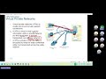


![[EN/ESP] EP.14-1 에이티즈 1탄 | 돌아온 에이티즈의 K-매운맛 시간 여행! 무법자들의 고추 가방 쟁탈전🌶️ | 돌박이일 ATEEZ in 천안 [4K] image](https://i.ytimg.com/vi/Qykl7vDHHsA/default.jpg)